The Idea Is Born
In my opinion, an ideal alarm clock should: have an easy-to-read time display, produce a very loud and annoying ring, be able to set alarms with multiple criteria, and, of course, tell the time accurately. Most alarm clocks on the market satisfy no more than two of these criteria: very basic analog alarms are very loud and have good displays, but are technologically very “dumb” and are not exactly accurate, digital alarm clocks also have good displays and decently loud alarms, but are similarly dumb and inaccurate, and “smart” alarm clocks like Amazon’s Echo line are smart and accurate, but usually lack a good time display or loud alarm. It was because of this lack of good alarm clocks that I decided to make my own in the fall of 2022 using a wifi-connected microcontroller to keep time accurately and a disassembled analog alarm clock bell mechanism to sound the alarm.
The Hardware
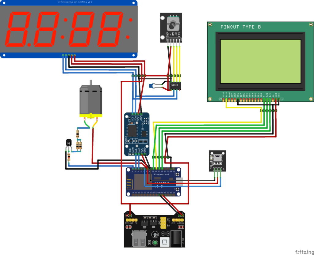
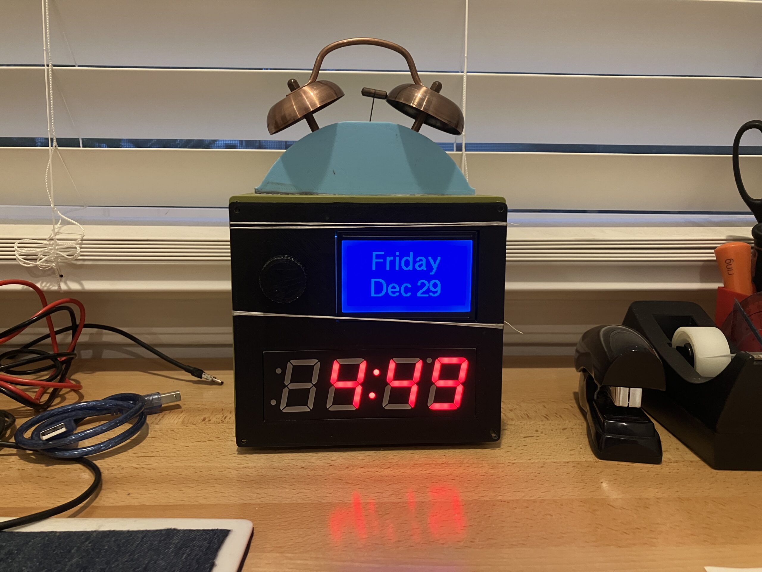
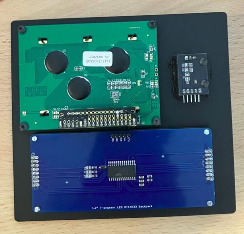
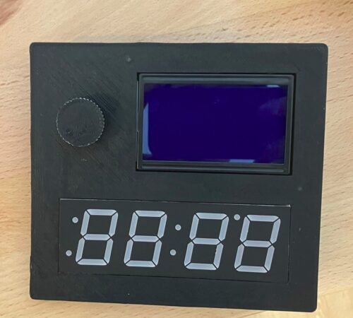
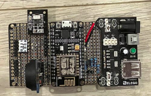
As mentioned previously, the alarm clock is controlled by an ESP8266 NodeMCU, a wifi-connected microcontroller board that allows for time synchronization and setting complex alarms. The time is displayed on a 1.2″ 7-segment LED clock display, and a 128×64 LCD (uncoincidentally also the type used in 3D printers) is used as an additional interface. User input is through a rotary encoder or IR remote.
The whole clock is powered by a breadboard power supply that outputs both 5V and 3.3V since the ESP8266 runs at 3.3V while the LCD and LED displays need 5V to function. To keep time throughout the day and in periods of no WiFi, a DS3231 real-time clock is used. Every night, the time is synchronized via NTP (Network Time Protocol) and is stored in the RTC, which is used to tell time during the rest of the day.
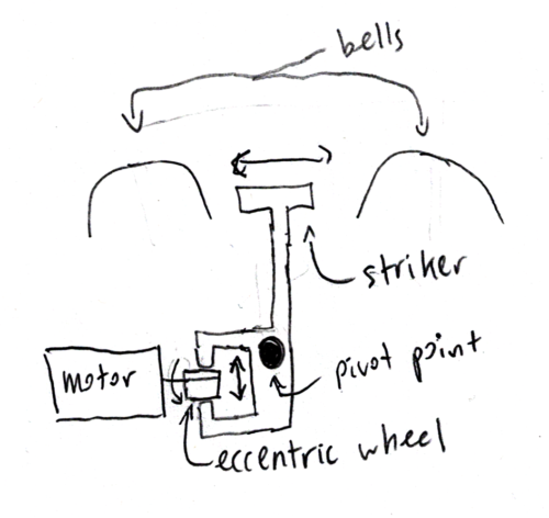
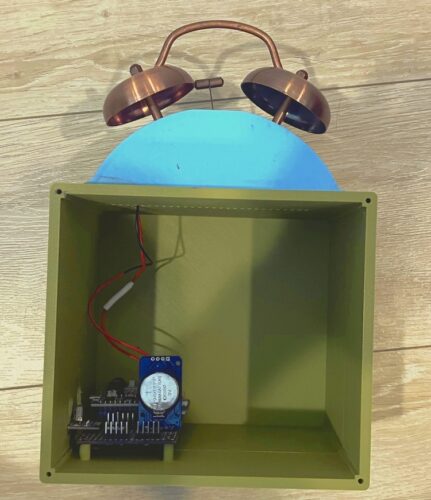
The actual component that sounds the alarms is made from an old analog alarm clock. It consists of a motor with an eccentric wheel that drives a striker side to side between two hemispherical bells. These components were removed from the original clock and screwed into a 3D-printed housing. The motor is driven by a PN2222A NPN transistor and three 10Ω resistors (two in parallel and one in series) are used to limit the current. (In the original alarm clock, the motor was connected by a set of contacts directly to the battery.)
The ESP8266 doesn’t have that many usable GPIO pins. Two are taken up by I2C, which are used to communicate with the RTC and clock display, and four more are used for the SPI-connected 12864 display. (Technically SPI only takes up three, and one is used to control the backlight.) Then the IR receiver and alarm clock take up one more each, and there are no more pins left. For this reason, a Serial Wombat 4B I2C expander is used to read the input from the rotary encoder. Since an I2C bus already exists, we can simply hook up the Serial Wombat to that, using no additional pins.
Parts (NOT an exhaustive list):
- 1x Adafruit 1.2″ 4-Digit 7-Segment Red LED Display w/I2C Backpack
- 1x 12864 LCD display (I think the driver is the ST7920, but don’t take my word. Many sellers don’t list the driver chip)
- 1x KY-040 rotary encoder module
- 1x DS3231 RTC module
- 1x old bell alarm clock
- 1x IR receiver (standalone or on breakout board are both okay, the breakout board version has an LED to tell you when it’s receiving)
- 1x Serial Wombat 4B
- 1x MB102 5V and 3.3V breadboard power supply (it takes between 6.5VDC and 12VDC input and is a linear converter)
- 1x ESP8266 NodeMCU
- Pin headers, male and female
- 24-gauge solid wire
- 1x PN2222A NPN transistor
- 3x 10Ω resistor
- 1x 1kΩ resistor
- 3x 2-56×3/8 screws (to attach circuit board to case)
- 4x M3×12 screws (to attach front panel)
- 4x M3x6 screws (to attach LCD)
- 4x M2x6 screws (for clock display)
- 2x M3x14 screws (for rotary encoder)
The Software
I’ve put the code for my project on GitHub here. The entire coding process was very dull and I certainly won’t write about every time I forgot a semicolon, but I will share some interesting parts.
Each alarm is stored as a struct (basically a data type of its own with certain attributes to it). Like all alarms, you can set the hour, minute, and second of the alarm. You can also set any combination of the seven days of the week, which is stored in a byte variable. (Since there are seven days of the week and eight bits in a byte, each bit (save one) corresponds to a day of the week.) Then, to allow even more flexibility, you can set upper and lower limits for which days of the month to ring on as well as any combination of the months of the year. Finally, you can set a message to display when the alarm rings.
Consider the following example: daylight savings starts on the second Sunday in March, and I want to be reminded to set the clocks at 5:00 PM. So I’d set the time to 17:00:00, the day of the week to Sunday, and the month to March. To build in the “second Sunday” logic, consider the following extreme examples: 1) The first day of the month is a Sunday, so the second Sunday occurs on the 8th. 2) The first day is a Monday, so the second Sunday occurs on the 14th. I can confidently say that the second Sunday will always be at least on the 8th and at most on the 14th, which is what I set the low and high month days to.
The menus on the clock are designed much like those of a 3D printer. Twisting the rotary encoder scrolls through menu items and highlights them. Pressing the encoder selects the item, either executing a command, going to a submenu, or editing a variable.
Each menu in the clock is stored as several arrays. One stores the names of each item, and another stores the variable (if applicable) that is displayed to the right of each item. Specifically, the variables are stored as void* pointers in one array while another contains the types of those pointers. Finally, there is a function that executes menu commands depending on what menu item was selected. Going to a submenu and entering “variable editing mode” are treated as commands.
For example, let’s say a menu contains items “back”, “command” “submenu”, and “variable”. “Back” goes to the previous menu, so a “↶” arrow makes sense as something to show to indicate that selecting that item goes to the previous menu. “Command” executes a command, so it has nothing to the right of it. “Submenu” goes to a submenu, so the “→” arrow indicates this. Finally, “variable” shows and modifies a variable x.
The code for this menu probably looks something like this (all functions are made up):
int currentSelected = 3;
String menuItems = {"back", "command", "submenu", "variable"};
String backArrow = "↶";
String rightArrow = "→";
String nothing = "";
int x = 0;
void* pointers = {&backArrow, &command, ¬hing, &x};
int pointerTypes = {0, 0, 0, 1};
void obeyCommands(){
switch(currentSelected){
case 0:
goBack();
break;
case 1:
doSomeCommand();
break;
case 2:
goToASubmenu();
break;
case 3:
editVariable();
break;
}The Problems
The alarm clock definitely has a few problems I would address if I started over from scratch:
- It is too big. The inside of the case is mostly empty.
- There aren’t enough pins. I have used up every available pin in the ESP8266 and every available pin in a 4-channel I2C expander. There is no room for expansion unless I use another I2C expander
- The pins are chosen poorly. For example, every time you upload code, the alarm goes off for twenty seconds.
- The circuit board is bad. Part of this is to be expected— it is a prototype board. But regardless of this, the board is crowded, poorly planned, and poorly executed.
- The IR receiver is on the side. The reception is not as good as it could be, though an angled piece of aluminium foil next to the clock seems to help.
- Everything is screwed into plastic or glued. Nothing can be taken apart easily. Despite my personal philosophy that things should be repairable, this clock is not
Since the ESP8266 can connect to WiFi, I may make some ESP8266-based expansion boards in the future (for example a light sensor to tell what time of day it is) and connect them wirelessly to this clock to expand its functionality.
STLs
Bell case, bell lid, case, case front, encoder knob
Fritzing files
These files represent how I made the circuit. They are most certainly not the optimal design.