

A problem I have struggled with in sand casting is mold tear-out. Even in patterns with generous draft angles, the sand very often gets torn out when the pattern is removed. Although charts of green sand mechanical properties versus moisture content, fineness, composition, etc. are available (for example in the US Navy’s Foundry Manual), the sand that I use is a bit different from industrial foundry sands in that it is much coarser, but has a higher proportion of binder, which is just clay soil from my backyard. I suspected that the binder may have been causing excessive pattern sticking, so I decided to investigate the matter on my own.
In general, patterns resist being drawn from the mold for two main reasons: adhesion, which acts perpendicular to the pattern walls; and friction, which acts in-plane with the pattern walls. I tested adhesion by ramming a cylinder of sand on top of a plate, and found it did not adhere at all, so friction is clearly the main cause of resistance. Friction, in turn, depends on two factors: the force pressing the two surfaces together, which has to do with the plasticity and elasticity of the sand and pattern, and how hard it was rammed; and some magical “coefficient of friction” that is determined by the properties of the two surfaces.
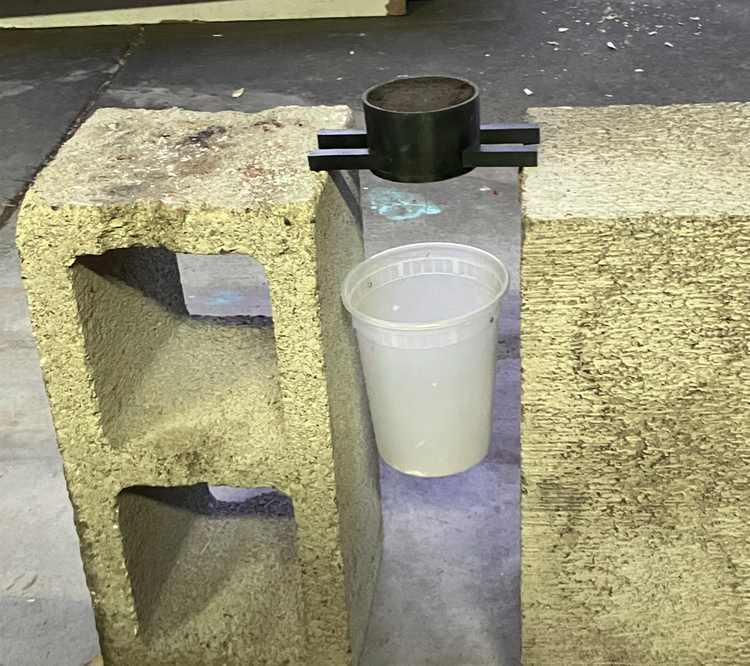
Pulling Force Test Setup
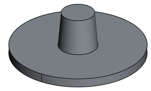
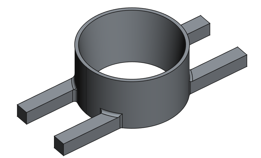
The test pattern was a frustum (a cone with the top chopped off) of average diameter 20 mm, height 20 mm, and draft angle 5°, attached to a plate. It was 3d-printed at layer heights 0.2 mm and and 0.1 mm, in vertical orientation and horizontal orientation (split down the middle and glued together). The flask had some negative draft to keep the sand from falling out, and arms extending left and right allowed it to be supported between some bricks so that the pattern could be pulled out from underneath.
The pattern was rammed using a 3/4″ steel bolt into a flask with some negative draft to keep the sand from coming out; it’d be preferable to have some way to standardize ramming, but that seems a bit beyond the scope of this project, and at any rate the actual ramming I do when preparing molds is not standardized.
Drawing force was measured by hanging a container from the pattern using a screw hook and slowly pouring gravel in using a half-section of 2″ PVC pipe as a chute, then weighing the container after the pattern fell out. This is an underestimation since the actual force exerted on the pattern is the weight of the container, combined with the force exerted due to the gravel’s change in momentum. Given this, I have absolutely no faith in the absolute numbers I obtained, though they’re still useful in comparison to each other.
When I first conducted this experiment, I thought that directly measuring the pulling force on the pattern would require some sort of tension gauge. In hindsight, I realized that it can be done with something I already have: a load cell I built (for strength testing on a drill press) has two spaced-out support beams and a big hole in the middle, so I could just put flask on the load cell and pull the pattern out by hand through the hole, measuring the force exerted by the pattern on the flask. I’m going to repeat this study using that method… sometime in the future.
Results
The data itself can be viewed in a spreadsheet here. As I said before, the data is pretty crappy.
Printing orientation
As expected, printing in a horizontal orientation (so that the layer planes are parallel to pulling direction) decreases drawing force, as does printing with finer layers. Given that vertically-printed patterns require no assembly and are usually simpler to print, I think that printing vertically at 0.1 mm layer height seems a good solution for most patterns, balancing printing ease/time, ease-of-assembly, and drawing force.
Surface preparation and parting compounds
Rough sanding did not improve drawing force except for the sample printed horizontally at 0.2 mm layer height, so it is generally not a good idea.
I also tried a variety of commonly-available powders as parting compounds: cornstarch, charcoal, calcined plaster, diatomaceous earth, and vegetable oil. For models printed vertically at 0.1 mm layer height, they had basically no effect on drawing force, possibly even increasing it.
However, parting powder did appear to have a positive effect where the 3D-printed surface was rough to begin with, that is, in the sanded sample, and the sample printed at 0.2 mm layer height.
Tests on Water Content and Clay Content
Let me start by saying that water content is calculated as a mass percentage of green (i.e. moist) sand, whereas clay content is calculated as a mass percentage of dry sand. The difference is not that important for low clay/water contents.
There are a few factors that influence how much water a sand should have, mainly permeability and strength. Because my sand is so coarse, I think it’s safe to ignore permeability and just select the moisture content that gives the highest strength. And although a sand’s compressive strength is not always positively correlated to tensile strength, I’m only considering compressive strength because that is the factor that is easier to measure, and thus more data is available on it.
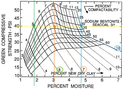
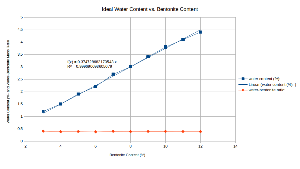
Taking the data from this chart and plotting bentonite content vs. water content at which maximum compressive strength is obtained, we get a linear relationship with a ratio of 0.37 percent water per percent bentonite (as measured by the preceding definitions of water and bentonite content). The water:bentonite ratio is calculated by the formula \( \frac{\text{water content}}{(1-\text{water content})\text{bentonite content}} \), and it remains pretty much constant at 0.39 across the data set.
When I actually tried varying the clay content, I found that there is a very narrow “sweet spot” of around 12% clay. Any less and there is not enough clay to evenly coat the sand grains (at least, when the sand is “mulled” by hand), and the sand will not stick together; any more and the greensand does not crumble apart readily so that it can be reused. I also found an unexpected benefit of having black clay: you can tell when the sand grains are fully coated with clay when the greensand appears fully black — even though there is much less clay than sand (which is white).
Discussion of Ramming Energy
In industry, sand specimens are prepared by putting greensand in a tube (50 mm ID) with a rammer on top, then dropping a weight of 64 N from a height of 50 mm onto the rammer 3 times. This is supposed to be a reliable simulation of how sand is usually rammed in foundries. An alternative method referenced in this paper is to use molding pressure, compacting the sand to a predetermined pressure. I would imagine that this method is a good simulation of industrial mold-making machines, but is less reliable for rammed molds because different sand elasticities would result in different maximum pressures developed in the sand for a given energy load (the rammer impacting the sand).
To determine the energy load developed by my own ramming, I took inspiration from Randall Munroe’s chapter about throwing things from How To, which gets pretty accurate results by assuming a human being accelerates an object under constant power. The expression for final energy is
\[ \frac{1}{2}\sqrt[3]{9(m_{object}+0.001m_{person})P^2x^2} \]
where power can be calculated as a function of the person’s weight, and adding \( 0.001m_{person} \) is to account for the mass of the person’s hand.
Assuming I’m ramming with 30% of my strength, across a distance of 0.3 m, and I weigh 60 kg and can output a maximum of 10 W/kg, then the energy developed from using my 0.131 kg rammer is 8.6 J. The cross-section of my rammer is 35 mm × 35 mm square, and I usually ram layers of sand about 30 mm deep, so I deliver about 230 000 J/m3 to the sand in each ramming. By contrast, the energy developed by the controlled specimen-rammer is 3.2 J, with a cross-sectional area of 0.00196 m2 and a depth of 0.05 m, giving 33 000 J/m^3.
8 responses to “DIY Greensand Properties Testing — Preliminary Results”
reglan
reglan
stromectol best price
stromectol best price
cialis for prostate
cialis for prostate
meloxicam 7.5 mg cost without insurance
meloxicam 7.5 mg cost without insurance
fluconazole 200 mg tablet
fluconazole 200 mg tablet
trimox
trimox
metoprolol succinate xl
metoprolol succinate xl
lasix diuretic for dogs
lasix diuretic for dogs