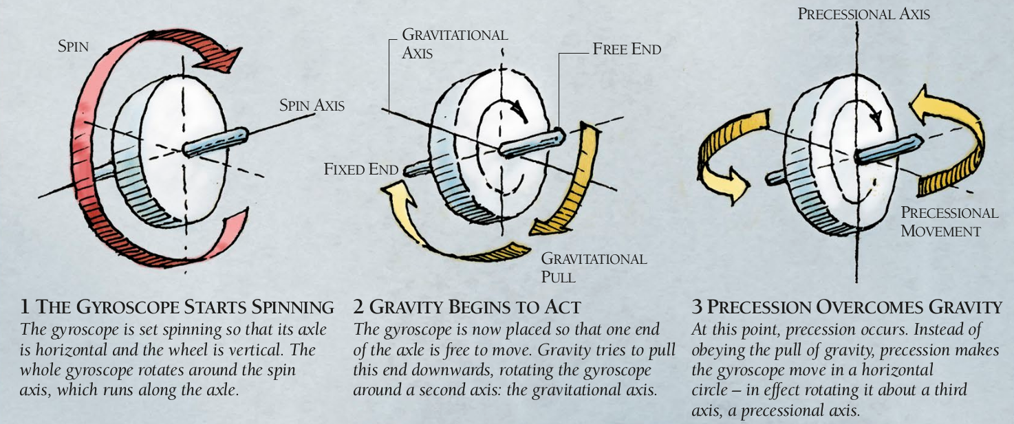
A spinning gyroscope can balance on a pivot, defying gravity by remaining horizontal while resting just on the tip of its axle. Instead of falling off the pivot, the gyroscope circles around it. The explanation for this amazing feat lies in the effects of precession. Like all other objects, the rotating wheel of the gyroscope is subjected to gravity. However, as long as the gyroscope spins, precession overcomes gravity by transforming it into a force that causes the gyroscope to circle instead of falling.
The Way Things Work by David Macaulay and Neil Ardley
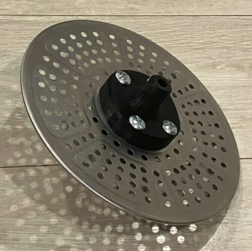
At the suggestion of my physics teacher, I decided to make a gyroscope as a classroom prop. I’m not completely sure what he expected when he asked me to make one, but this project is the result. After considering several designs including a cast zinc rotor and a 3D-printed rotor weighted with coins, I settled on using the air fryer tray from an Instant Pot® air fryer as the rotor, with zinc weights to increase its moment of inertia. It was light, but relatively stiff, and importantly, already had lots of holes poked in it for mounting things.
Bearings and Shaft
The gyroscope has to be supported by a shaft upon which it can spin freely but not slide or wobble too much. I did this by 3D-printing custom “pillow blocks with integral bearings” (a.k.a. blocks of plastic with holes for mounting screws and a shaft) with the mounting holes aligned with the holes on the rotor. To allow for precise mounting, the back block’s mounting holes were flanged to the exact diameter of the rotor’s holes, while the front’s were counterbored to fit the flange.
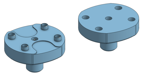
My intention was to use a 5/16″ (7.937 mm) shaft, the largest common shaft size that could fit the 8.4 mm center holes of the rotor. I modeled the pillow blocks with holes of exactly 5/16″, knowing that the 3D printer would undersize them somewhat, with the intention of drilling them to size. Unfortunately, I didn’t account for the fact that the shaft would be 0.06 mm oversize (about 8.00 mm diameter), so even after drilling out the bearing hole, the shaft refused to enter.
Now, the ideal tool to solve such a problem, for $10–20, would be a reamer. Since a) I don’t buy things if I can avoid it, b) a reamer is just a cylinder with a bunch of cutting edges cut out of it, and c) the shaft was literally a cylinder of metal the exact diameter desired, I decided to cut a reamer out of it. Now, to call it a “reamer” would be extremely generous: it basically had a single, very short (~5 mm) flute cut into one side by making two cuts with a hacksaw, with a cutting edge formed by “relieving” one side of the flute with a file to allow it to get under the plastic instead of just rub against it.

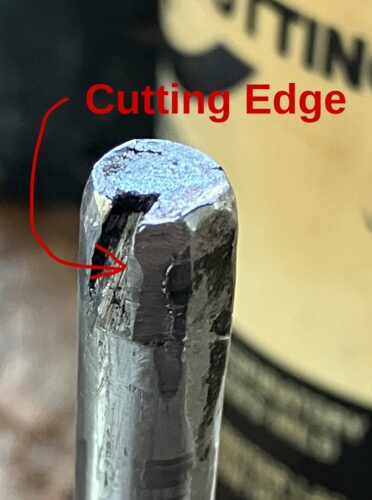
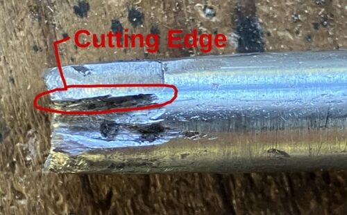
Practically speaking, this did the job, though since the flute was so short, it was necessary to ream the hole in many short passes, going very slowly to avoid heating the plastic too much, and bringing the tool out to manually pick out the chips from the flute after each pass. Also, to ream the hole very slightly oversize, I used a hammer to get flatten and widen the end of the tool slightly.
UPDATE: 2024-12-08
Machine Tool Operation has these much better instructions for making a reamer, though some steps can be disregarded when it is for plastic:
“A small-size reamer that will work well and can easily be sharpened may be quickly made from a piece of drill rod the size desired. Cut off to length, square the end, and round the corner somewhat. Then reduce the diameter a thousandth or two except for an eight of an inch or so from this end, either my filing or with emery cloth. Now bevel the end 46 deg. or more, leaving about half of it, back off the single cutting edge a very little and harden and temper. Grind and oilstone the flat beveled surface, oilstone the rounded cutting edge a trifle, and the reamer is ready to use. Feed slowly as there is only one cutting edge. “
The stock finish on the shaft was a bit irregular, so I smoothed it out by putting it in a hand drill and wet sanding it with 600-grit sandpaper. After lubricating the bearing and shaft with some PTFE lubricant, the rotor spun quite freely.


Next, I needed a shaft collar to keep the gyroscope from sliding around. Unfortunately, the set-screw type collars I initially bought didn’t fit because the shaft was oversized, and my DIY reamer failed to widen them (but not for lack of trying), so I had to buy some (much more expensive) two-piece clamping collars instead, which fit just fine.
Weights
I sand cast the weights from zinc. The patterns were 3D-printed. It was impractical to cast the 1/4″ mounting holes, so they were cast as divots used to locate the holes for drilling.
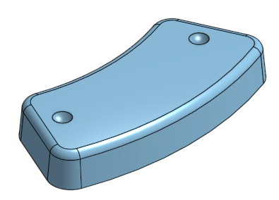
The repetition involved gave me a lot of chances to practice and feedback with ramming molds. There’s a whole blog post about that here.
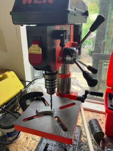
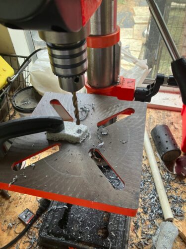
Drilling the holes proved to be much more difficult than intended; my 1/4″ drill bit was seriously dulled, so I had to learn (with lots of trial and error) to grind it on the face of a Dremel grinding wheel. Then, the bit kept rubbing against the sides of the hole and causing a lot of friction, and I needed to frequently apply small amounts of cutting oil (most of it gets flung out of the hole anyways) to lubricate it as well as drill the holes by “pecking”. On my first attempt I put way too much pressure on the drill bit, causing the casting to get very hot, and raising a large “burr” (if it can be called that) on the side where the drill bit entered. (This was probably because the heat from drilling made the zinc much more ductile, and the high pressure on the drill bit caused it to push material out of the way rather than cut through it.) Finally, this was the first time I found it truly necessary to clamp down the parts, which was done by first feeding the drill into the divot a little to locate the hole, then stopping the drill, locking the spindle down and clamping the part to the table with a C-clamp.

Assembly
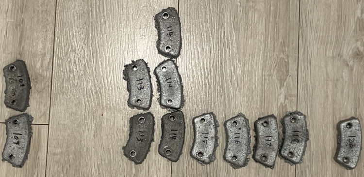
To balance the weight distribution on the rotor as much as possible, I weighed the 12 weights and selected 6 pairs that all had roughly equal masses, and then screwed them opposite sides of the rotor. The effect of this was most likely pretty small, since all weights were within 5% of the mean mass.
The pillow blocks were mounted first and then reamed to ensure that the holes would line up. Due to an unfortunate accident, the first set of pillow blocks (which were printed with 30% infill and 3 walls and meant to be a first draft anyways) got somewhat melted, so I had to print, install, and ream another pair.
As mentioned, the masses of the weights were quite similar, so I didn’t really need to balance them. However, the rotor was a bit warped, so I had to true it up using an highly accurate and advanced truing stand consisting of two boxes upon which the axle was rested horizontally, and a book placed near the rotor rim so I could visually judge where the wheel was warped by spinning the wheel and watch the gap change in size.

Although there are many tricks that you can do with a gyroscope, I designed this one to do the one described in the quote from The Way Things Work: supporting it on one end by a string and having it circle around instead of falling down.
Apparently, the formula for precession rate in these circumstances is given by \(\frac{rmg}{l\omega}\), which says that:
- The larger the radius of precession (i.e. the farther from the rotor’s center of gravity you support it) is, the faster it will precess.
- The larger gravitational force on the rotor (equal to mass times gravitational acceleration) is, the faster it will precess.
- The larger moment of inertia (which describes the rotor’s resistance to changes in angular velocity and is equal to the mass of the weights and their distance from the rotational axis squared) is, the slower is precession
- The faster the rotor spins, the slower it will precess.
I cannot at this time even pretend to understand the physics involved, so I’ll just wave my hand and say that slow precession indicates a greater ability to resist the torque exerted on the gyroscope by gravity, and that is what I want so that the demonstration will run for as long as possible.
There’s not much that can be tweaked about the rotor’s moment of inertia and gravitational force, though I did put the weights around the rim to take advantage of the fact that any mass far from the axis of rotation adds comparatively more moment of inertia.
To hang the gyroscope on a string, I initially just tied an icicle hitch to the shaft as close to the rotor as possible. However, this was still too large of a radius to give satisfactory results (the gyroscope precessed for barely 1 turn), so I had to use a shaft collar to clamp the string right up against the collar restraining the pillow block.
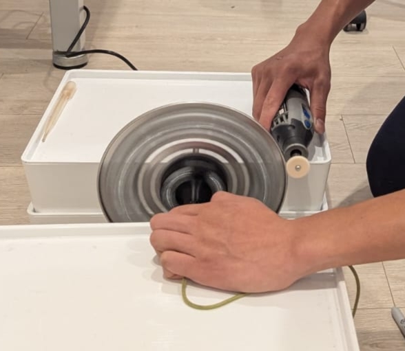
Finally, I tried a few different ways of spinning the gyroscope up. Doing it by hand and using the chuck of a cordless drill with a bit of bicycle-tube stretched around it to drive the edge of the rotor gave similar results. Much better was spinning it up using the large felt wheel from a Dremel at maximum speed — at this rate, the gyroscope started to vibrate extremely noticeably and throw off air currents, though this didn’t affect performance too much.
I also tried creating my own friction wheel (a rubber-coated wheel) by stacking two fender washers, stretching a piece of bicycle-tubing over them, and attaching them to a mandrel. At first, it was too unbalanced, but after filing it a bit while spinning it up, and taking apart the tool to put some rubber pads around the motor to cushion it against rattling about, it was mostly resolved. However, using it to spin up the gyroscope put too much load on the Dremel, and anyways the rubber kept slipping off. I think the felt wheel worked better since it could slip more, acting as a clutch to spin up the gyroscope by kinetic friction and avoid putting too much torque on the motor.

One response to “DIY Gyroscope”
[…] made a gyroscope. Part of that involved casting 12 zinc weights to go around the rim of its rotor, which gave me a […]