
One of the greatest advantages of AC power over DC is the ability to change its voltage by way of a transformer. However, transformers are bulky and expensive, especially variable transformers that allow household AC voltage to be lowered to throttle various electronic devices. But you can cheat: instead of varying the voltage, you can switch the power on and off to “chop off” part of each AC half-wave, effectively varying the voltage (though the output is not perfectly sinusoidal), with results that are good enough for many applications.
Theory
I found this very helpful article describing most of the design considerations involved in phase-fired control. This article was also helpful to me.
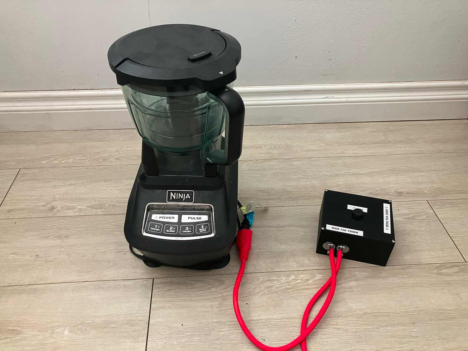
A TRIAC is a thyristor (a sort of latching transistor) that works in both directions. It latches on when a pulse of current flows through the gate, staying on until the current through it goes to zero. (I got mine (this one) from an old blender, which used it to control a universal motor.) We usually describe TRIACs as having “quadrants” of operation, with the x-axis representing current flow through gate and the y-axis representing current flow through the main terminals. They work best when gate current and main terminal current are in the same direction, but the one I have also works in quadrant II, where gate current is negative but main terminal current is positive.
Triggering It
Probably the most common way to trigger a TRIAC with a microcontroller is through an optocoupler, electrically isolating the high-voltage AC from the delicate microcontroller. By using a TRIAC-based optocoupler, it can control current in two directions, so you can use it to control the AC line voltage which is used to switch the TRIAC. However, with inductive or capacitive loads, the voltage-current offset means that voltage may reach zero at a different time that current reaches zero, causing triggering to fail. In this case some phase-shifting circuitry is needed to essentially re-align the triggering voltage with the current, and it must be customized to the expected load’s power factor.
Instead, as this very helpful article explains, it is much easier to trigger the TRIAC with a microcontroller by connecting the 5V pin to AC neutral, so that pulling an output pin to ground pulls it negative with respect to the TRIAC, allowing it to be switched in quadrants II and III.
Zero-Crossing Detector
Timing the TRIAC requires you to detect when it turns off, then vary the time that passes before you trigger it again. One common way to detect this “zero-crossing” is to use an optocoupler with its input driven by the rectified AC line voltage; adding a current-limiting resistor means that, because of the optocoupler’s exponential current-voltage curve (at a certain voltage current increases very rapidly), it will turn on without damage across a wide range of input AC voltages and turn off only when input voltage is very close to zero.
Another option is to use the microcontroller’s analog input to read the incoming voltage. By connecting the AC voltage to the analog pin using a large resistor, and using two smaller resistors to “pull” the analog pin to both 5V and ground, the bipolar AC waveform can be “clamped” upwards, eliminating the need for a rectifier.
It is most common to use incoming line voltage to time the TRIAC’s triggering, but with inductive or capacitive loads, this can lead to erratic operation due to the aforementioned voltage-current offset. Instead, a better solution is to directly detect when the TRIAC turns off by measuring its voltage drop. When the TRIAC is on, it’s about 1 V, but when it turns off, all the AC line voltage drops across it.
Snubber
One final design consideration is that TRIACs can usually be triggered on by a fast change in voltage, which occurs in inductive loads right as the current goes to zero and the TRIAC switches off. Normally a capacitive “snubber” circuit is required to be connected across the triac to correct this. Most basically, it resists changes in voltage; on a deeper level, it shifts the phase (i.e. timing) of the voltage across the TRIAC to avoid that rapid change right when it switches off. However, the “snubberless” TRIAC I’m using is designed to handle the fast voltage change, so a snubber is not needed.
Cooling
My TRIAC has a maximum continuous current rating of 20 A, but this assumes it can be cooled fast enough. But with a thermal resistance of 60 °C/W between the case and air, and a maximum junction temperature of 150 °C, the TRIAC can only dissipate about 2.2 W before overheating if it’s installed with no heatsink or active cooling. Since its voltage drop is about 1 V, this equates to 2.2 A of maximum current, which delivers about 260 W (roughly three big incandescent lightbulbs) to the intended load. I intend to use this phase-fired controller for much larger loads than that (mainly to control appliances with universal motors), so some cooling is clearly needed.
Construction
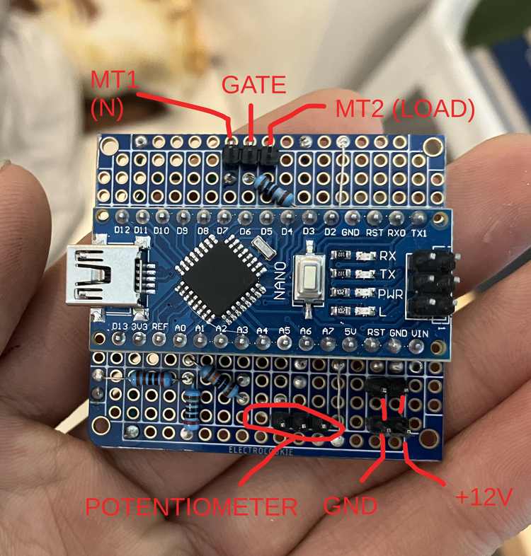
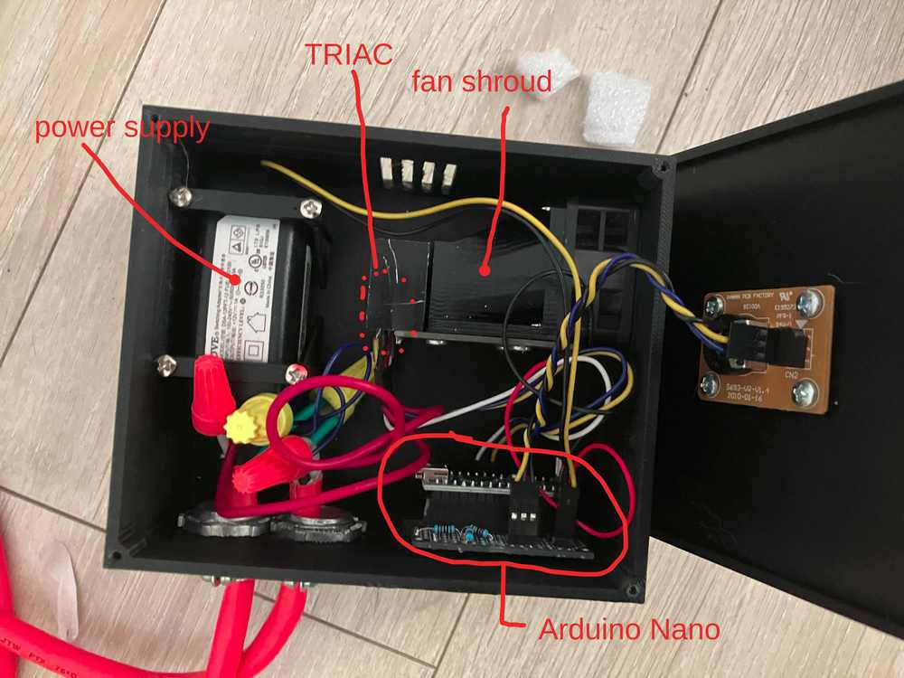
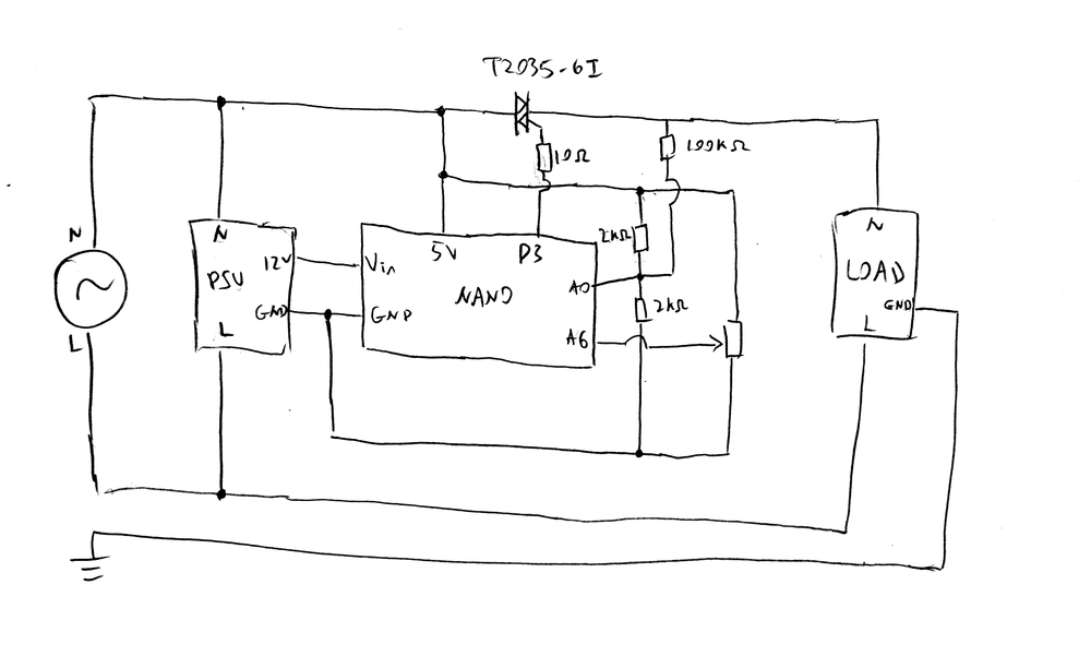
An Arduino Nano is used to control everything. Its analog input is used for zero-crossing detection, an IO pin to trigger the TRIAC, and user input is provided by a potentiometer. A 12V wall-wart power supply powers the Nano and the fan; its output is galvanically isolated from the input by means of a transformer, so it’s alright that +5V is pulled to neutral.
As mentioned before, the zero-crossing detector works by measuring the voltage across the TRIAC. When it exceeds 5 V, the Nano waits for some time (based on the input potentiometer), and then fires the TRIAC by pulling the gate low through a 10Ω resistor for 100μs. At the extremes of the potentiometer, the Nano is coded to fire immediately after a zero-crossing is detected, or never.
For cooling, the TRIAC is attached to a heatsink salvaged from an L298N DC motor controller, with a 40 mm fan blowing on the heatsink through a 3D-printed fan duct. Experimentally, the case temperature of the TRIAC at various currents is as follows, with an input air temperature of about 23 °C:
| Current (A): | Case temperature (°C): |
|---|---|
| 5 | 32 |
| 7 | 35 |
| 9 | 39 |
| 10 | 45 |
| 11 | 48 |
| 13 | 54 |
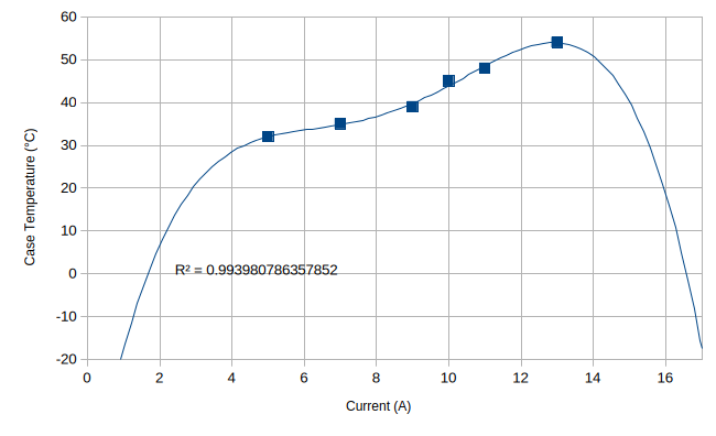
Increasing current up to 17 A will cause the case temperature to drop to nearly 0 °C.
When connecting this controller to a universal motor, it has the tendency to send a pulse of high current right when the motor is turned on, regardless of how low the controller output is turned to. I suspect this has something to do with the zero-crossing detector needing time to synchronize with the current: the code “assumes” that the current zero-crossings occur at the same time as voltage zero-crossings when there’s nothing plugged in. However, the issue doesn’t appear when the the motor is slowly ramped up from the controller’s off state. Converting the controller to a voltage-based zero crossing detector would probably fix the issue, since the input voltage is the same, regardless of the load, so there is no need for synchronization.
Another small issue inherent to this controller’s design is that the TRIAC doesn’t latch on unless sufficient current is being drawn.
Code
const int triggerPin = 3;

//r1 is connected to 5v and the analog pin
//r2 is connected to input AC and the analog pin
//r3 is connected to ground and the analog pin
//note that AC neutral is connected to 5V, so line voltage is 5V relative to Arduino when it is 0 relative to neutral.

const float r1 = 2000;
const float r2 = 100000;
const float r3 = 2000;
const float zeroVoltage = 1024.0 * r3 / (r3 + 1/(1/r1 + 1/r2)); // the analogRead() value when AC voltage is 0
const float zeroVoltageThreshold = 5.0; //how many volts must be across the triac before it recognizes that it's turned off
const float zeroThreshold = zeroVoltageThreshold / r2 / (1/r1 + 1/r2 + 1/r3) * 1024.0 / 5.0; // how many ADC bits for that voltage threshold

const int upperBound = (int) (zeroVoltage + zeroThreshold);
const int lowerBound = (int) (zeroVoltage - zeroThreshold);

const int triggerTime = 100; //in microseconds
const int maxDelay = 8333 - triggerTime - 750; //if you delay too long, it can trigger the next half-wave. That would be bad.

void trigger(){
  digitalWrite(triggerPin, LOW);
  delayMicroseconds(triggerTime);
  digitalWrite(triggerPin,HIGH);
}

int voltage;

void waitForZero(){
  while(true){
    voltage = analogRead(A0);
    if(voltage < upperBound && voltage > lowerBound){break;}
  } //wait for voltage across triac to go to zero.
}

void waitForOff() {
  while(true){
    voltage = analogRead(A0);
    if(voltage > upperBound || voltage < lowerBound){break;}
  } //wait until current flow stops, when voltage rises above some level.
}

void setup(){
  pinMode(triggerPin,INPUT_PULLUP); //this ensures the pin is already pulled high when pin mode is switched to output, avoiding accidentally switching on the triac.
  pinMode(triggerPin,OUTPUT);
  digitalWrite(triggerPin,HIGH);
}

int potValue;
void loop(){
  waitForOff();

  potValue = analogRead(A6);
  if(potValue < 15){trigger();} //trigger immediately; allows you to kind of use it as a switch
  else if(potValue > 1013){ while(analogRead(A6) > 1010){}}//do not trigger at all if potValue is too high; allows you to turn off the device
  else{delayMicroseconds(map(potValue,15,1010,0,maxDelay)); trigger();} //otherwise just do normal phase-fired control

  waitForZero(); //Prevents mis-timing right when the device is turned on.
}
9 responses to “Phase-Fired Controller”
erythromycin eye drops
erythromycin eye drops
synthroid
synthroid
atorvastatin 10 mg
atorvastatin 10 mg
levitra 20mg
levitra 20mg
what is doxycycline
what is doxycycline
dutasteride for hair loss topical
dutasteride for hair loss topical
sertraline hcl 25 mg tablet
sertraline hcl 25 mg tablet
augmentin 875 mg
augmentin 875 mg
furosemide 40 mg tablet
furosemide 40 mg tablet