
Introduction
This post describes a project I did in the past. It was the first project that I did more-or-less independently of parental encouragement, and I learned a lot of skills in the process. I’d say that this project is the precursor to all my other projects.
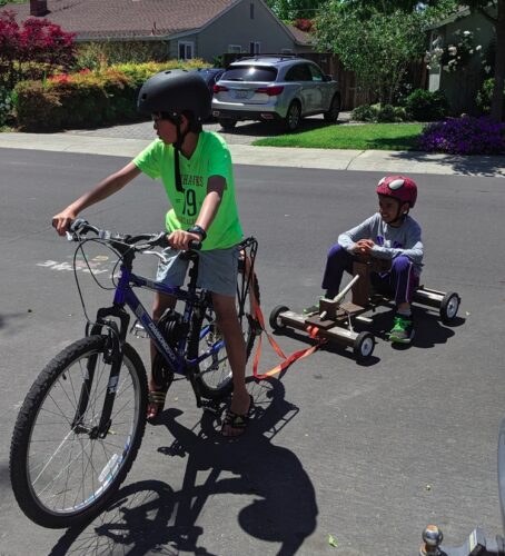
At some point, my mom bought a wooden go-kart. The frame was built in an “𐌆” shape with a string wrapped around the steering column (a dowel) moving the swivel-mounted front wheels, kind of like a bow drill but in reverse. A brake lever pulled a cable that pulled a wooden board against the rims of the two rear wheels. Lacking a power source, we pulled this go-kart along on some ratchet straps using a bicycle.
Sometime after this, we decided to make another kart, this one drill-powered (like this one featured by Make magazine) because it seemed like a cheap and simple power source. Its frame was built almost identically to the first but larger, and we planned to power the go-kart by using the drill’s chuck sleeve (the part that you turn with your hands) to engage the rear wheel. Unfortunately, this didn’t exactly pan out since the drill was too weak to effectively drive the kart.
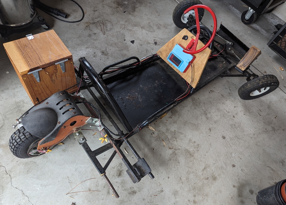
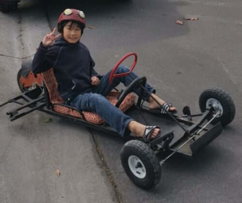
Unwilling to admit defeat, my mom found a broken-down electric go-kart on Nextdoor. It consisted of the steel frame for what used to be a gas-powered go-kart, with the rear wheels removed and the rear section of a cheap electric scooter attached. Three lead-acid batteries that once powered the 36 V 30 A brushed DC motor had cracked and their electrolyte leaked out long ago. The accelerator was the original twist throttle from the electric scooter, mounted next to the steering wheel, and the brake used the original pedal from the gas go-kart to operate the scooter’s disk brake, though the end of the Bowden cable housing had become detached from the frame, rendering the brake inoperable. The steering system used a bell-crank steering mechanism, in which a crank arm at the end of the steering column directly moves two connecting rods attached to either front wheel in and out. The individual electronic components (accelerator, batteries, motor, charging port) connected to a control box, basically some MOSFETs and other circuitry housed inside an aluminium box, which drove the motor.
Initial Improvements
To start we bought three new lead-acid batteries and wired everything up, re-mounted the throttle, and fixed the brake by replacing the old brake tube/cable, epoxying the brake tube ferrule to the frame to fix it in place, and clamping the cable to the brake pedal using a screw and fender washer. The batteries were held in the cardboard box they were delivered in, strapped to the frame with bungee cords. It worked perfectly except that the throttle tended to get stuck in the fully open position.
Of course, now that I knew the go-kart worked, I had to improve it. First, I made a wooden box for the batteries, measuring and cutting each side to exactly the required dimensions without accounting for tolerances. Predictably, the batteries didn’t fit, so I had to spend a few days using an electric sander to make the inside of the box just a little bit bigger. It was then carriage-bolted onto the frame using the holes originally intended for an engine.
I also decided to get a throttle pedal instead of relying on the old twist throttle. After removing the old throttle pedal from the gas go-kart which didn’t connect to anything, I ruined at least one drill bit drilling mounting holes through the frame, not realizing that the spindle speed was too high and I wasn’t applying enough pressure. After mounting the throttle, we found that it worked, but the pedal was sitting too flat, which was fixed by screwing a wooden wedge to the pedal’s surface, raising its angle.
For reasons I cannot recall, we also replaced the controller. Since its battery and motor connectors differed from the original ones, I simply snipped off the original controller’s connectors and solder-spliced them to the new one, with some difficulty since the wires were very thick and my soldering iron wasn’t very powerful. I also cleaned up the messy and janky wiring the go-kart came with.
Speedometer
This was all going very well, so to take the project one step further, I decided to add a speedometer.
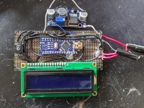
Although you can buy speedometers rather cheaply on Amazon, I thought it would be a good idea to try to make one myself using a magnet mounted to some spinning component and a hall-effect sensor to detect how frequently it passes a given spot, giving the rotational speed of the wheel, which is used to find the linear speed. An Arduino Nano was used as the processor and the result was displayed on a 16 × 2 character LCD. It was powered by the go-kart’s battery, with the voltage reduced through an LM2596 buck converter. Additionally, a voltage divider allowed the battery voltage and (rather inaccurately) state-of-charge to be read by the Nano’s analog input and displayed.
The circuit itself was messily prototyped on stripboard; a lack of previous planning meant the final circuit board had a lot of connections made with wires rather than the existing connections on the board. The hall effect sensor was mounted (and potted with hot glue) on a separate circuit board that was screwed to the rear wheel assembly facing the rear sprocket, which had a neodymium magnet superglued to its face. All components of the speedometer were connected with some thermostat cable.
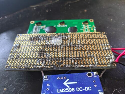
Probably the most time-consuming and educational part of building the speedometer was 3D-printing the case since it was the first time I’d used the printer for anything practical. After lots of trial and error, I produced a very poorly designed (it was modeled in TinkerCAD) prototype case. The circuit board sat on little 3D-printed mounting pins whose ends were mushroomed with a hot screwdriver to permanently fix it in place. Then, the case was covered with a 3D-printed lid consisting of a rectangular plate and a cut-out hole covered with clear plastic for viewing the LCD. This lid, which lacked screw holes, was then welded to the case using a 3D Doodler pen (a 3D printer hotend/extruder packaged in pen shape). Finally, I’d forgotten to add screw holes to mount the case to the “instrument cluster”, so I had to 3D print a bracket to hold it in place.
Reversing, Batteries, and Capacitors
Additionally, to give further maneuverability to the go-kart, I added reversing capability.
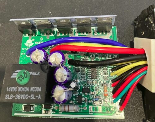
To reverse the brushed DC motor of the go-kart, you simply had to reverse the polarity applied to it. To try this, my first thought was to reverse the input voltage of the controller. As soon as I plugged in the last terminal to complete the circuit, there was a loud “pop” and a puff of smoke, and the spade terminal I’d just tried to plug in was completely gone.
What happened was that unbeknownst to me, the go-kart controller had a few large electrolytic capacitors installed across the input terminals. They were charged up when the battery was plugged in the correct direction. Then, when the battery was quickly disconnected and reversed, a short circuit was completed with the capacitors effectively in series with the batteries, and the resulting momentary large current flow melted the battery terminal. To make matters worse, the capacitors, after discharging, found themselves connected in reverse, and promptly “released the magic smoke”.
After buying a new controller and a DPDT switch to reverse the output of the controller with a simple toggle, the reversing function was finally ready. Because mounting the reverse switch required reorganization of the “instrument cluster” I went ahead and designed a new speedometer case, this time in FreeCAD, which turned out a lot better.
Unfortunately, for some reason, after these modifications, the go-kart started running very slowly after just a few minutes of operation. Stopping it for a few minutes seemed to recover its speed, leading me to suspect the controller was overheating.
Suspecting that the new batteries were dead, I attempted to revive them by buying a smart battery charger and adding more water to the cells. (They were sealed lead-acid batteries, which usually never need refilling.) This just resulted in a loss of air space in each cell, so when the batteries were charging, gas generated in the process popped the caps off. After buying a completely new set of batteries, the problem was still not fixed.
I also used a clip-on ammeter to measure the current drawn by the motor, which was around its 30 A rating. In hindsight, I think the problem was that the go-kart controller I picked was under-specced similar to many cheap (Chinese) electronics found online. Unfortunately, I didn’t have this revelation until much later, and having hit what seemed like a brick wall, I abandoned the project.