
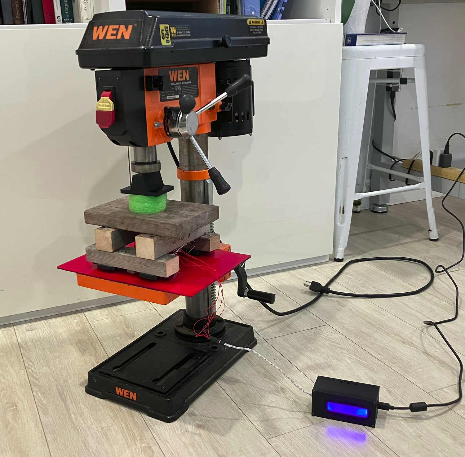
In a recent science fair project, I used a drill press as a press for strength testing.
Drill presses are designed to exert fairly high forces while keeping the spindle perfectly straight. Pretty much all drill presses also have some provision to measure downwards travel, allowing the measurement of strain. Additionally, the self-holding Jacobs taper used to mount chucks can be used to mount 3D-printed test fixtures. This all makes drill presses a good choice for a DIY compressive or flexural strength-testing machine that you may already have at home. Unfortunately, since the Jacobs taper will release if you use it to pull anything upwards, it can’t really be used for tensile testing.
To measure the force exerted, a load cell is needed. Commercial ones capable of measuring high forces are a bit pricey, so I made my own. It is essentially a glorified bathroom scale, using the same four inexpensive load cells, one under each corner of the wooden base. Put together, the load cells can withstand up to 200 kg of force, which is just about the maximum that can be comfortably exerted on my 10″ drill press.
The load cells are wired in a wheatstone bridge configuration. The circuit basically works like this: two strain gauges — one which increases in resistance as a load is applied, and one which decreases in resistance as a load is applied — are wired in series to make a voltage divider. When a load is applied, one strain gauge increases in resistance and the other decreases in resistance, changing the voltage at the voltage divider’s output. Since this output has a large offset (a baseline voltage much greater than voltage changes caused by changes in load), another voltage divider oriented opposite to the first (so that its output voltage changes in the opposite direction as the first) is added, and the voltage difference between them is measured. Both dividers have the same baseline voltage, so it cancels out when measuring the difference in voltage. (More information about the wheatstone bridge in load cells can be found here.)
Anyways, this voltage difference is measured by a very high-resolution HX711 ADC, which is read by an Arduino. In my science fair project, I simply strung the components together with jumper wires and outputted the weight to my computer over a serial connection, a very janky and fragile solution. Since I wanted to use this strength tester for other things, and the drill press normally lives on a very dirty workbench, I needed a more robust device for reading the load cell.
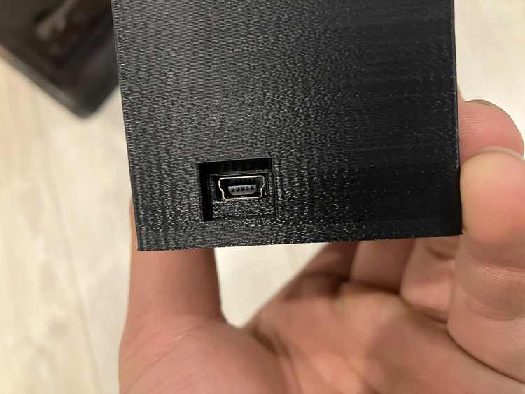
What I made was a 3D-printed box containing an Arduino Nano, the ADC, a 16 × 2 character LCD display, and some buttons. Because of a lack of mounting points for the circuit boards, the ADC and breakout board with the buttons were pressed into tight-fitting slots, while the Arduino Nano was mounted on some 3D-printed clips with its USB port (used to upload code and power the box) accessible from a hole in the side of the box. The LCD was set into the box’s lid, and screwed onto some standoffs. Some separate pushers are used to push the buttons from outside the box.
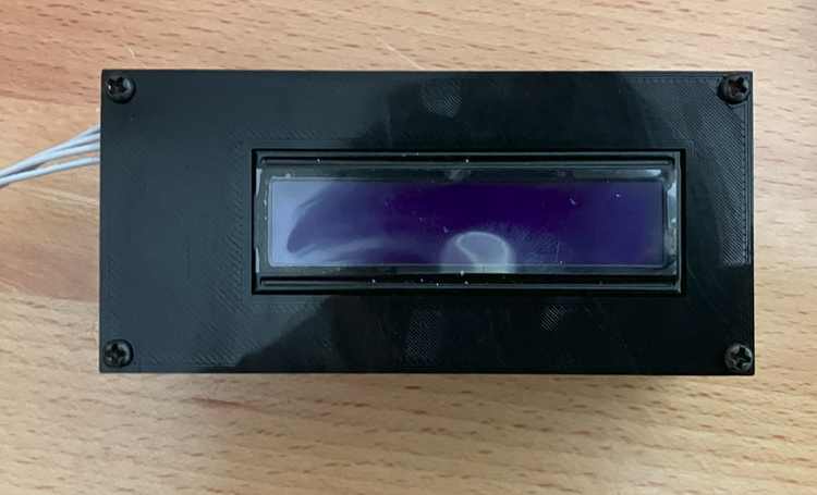
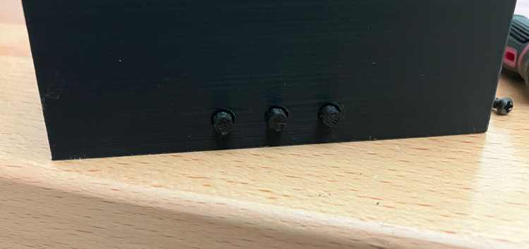
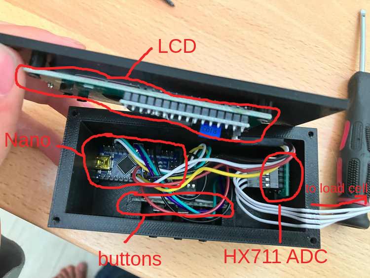
The LCD displays both the current load and the maximum load, and is updated only once every 300 ms to prevent excessive jittering, though the maximum load is updated much more often. The 3 buttons are used for taring the load cell, changing the display’s units (lb, kg, or N), and resetting the maximum value. Additionally, the box can connect to a serial console to log the load over time and calibrate the load cell. The calibration value is stored in the Nano’s EEPROM so it can be recalled even after power is removed.
2 responses to “Drill Press Strength Tester”
[…] hindsight, I realized that it can be done with something I already have: a load cell I built (for strength testing on a drill press) has two spaced-out support beams and a big hole in the middle, so I could just put flask on the […]
[…] previously used my drill press as a strength tester. Now, with two modifications, it can grind spade […]