
Summary
- Through trial and error, I found the print settings that allow very fine sieves to be 3D-printed effectively.
- I also devised formulas for determining the appropriate infill percentage and thickness of such sieves.
Introduction
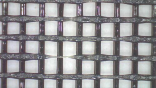
I recently found the need to sift store-bought sand to separate out the finer particles, with a targeted particle size of <0.4–0.5 mm (< 35–40 mesh). I considered using a kitchen sieve or a piece of window-screen, but found that they both had a hole size of about 1.5 mm (14 mesh), making them too coarse for my purposes. Since I couldn’t find any other easily-available sieves or meshes that were fine enough, I decided to 3D-print my own.
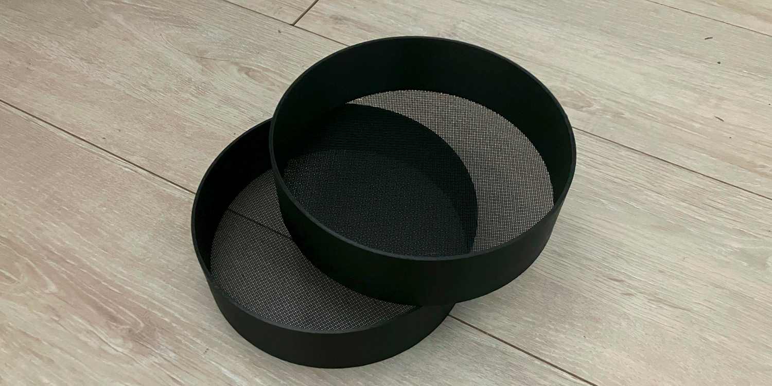
I printed circular sieves 150 mm in diameter, with a rim that was 2 mm thick and 40 mm high. The sieves were modelled in CAD with a solid bottom, and then the screen was generated using SuperSlicer’s infill patterns, by slicing the model with zero top and bottom layers.
Here is a STEP file for the sieve:
Print Settings
- Material: I printed my sieves out of PLA due to its convenience as the most common 3D printer filament. The sieves ended up sufficiently strong for their purpose.
- Infill Pattern: I tried using both grid and rectilinear infill patterns.
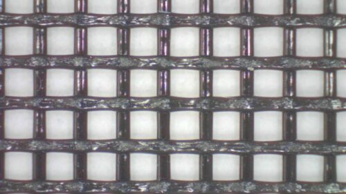
- Grid infill has better layer adhesion, giving it better flexural stiffness, making it better for coarse and thick sieves.
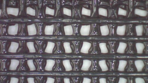
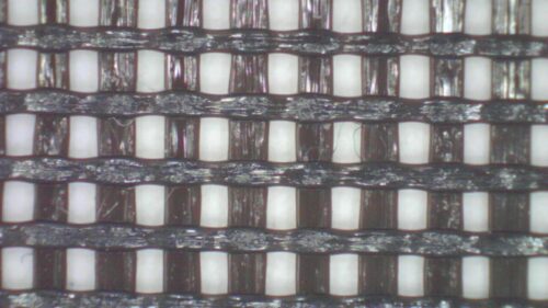
- However, grid infill causes material to accumulate at the intersections of extrusions, making it unsuitable for fine sieves, due to this accumulated material significantly altering the holes’ shape and size. Rectilinear infill is more suitable for fine sieves.
- Another potential infill pattern, which produces openings that are more nearly circular, is the “honeycomb” pattern. However, since its extrusions take a zig-zag path instead of being straight, it is much slower to print, particularly on a bed-slinger-style printer like mine with limited acceleration. I’d imagine that the zig-zags also make extrusions more difficult to lay down consistently.
- Raft: Due to the tendency for the first layer to get somewhat compressed, and for its extrusions to end up wider than intended, I found it necessary to print a raft.
- With the default z-contact distance of 0.1 mm, the screen’s extrusions weren’t consistently-spaced, so I reduced the contact distance to 0.02 mm to fix it. The raft could still be removed easily after this.
- I used a 2-layer raft, and found its thinness beneficial since it could be gradually peeled off to avoid damaging the screen.
- Layer Height: I found that with a layer height of 0.1 mm, the extrusions blobbed up and broke off, instead of being laid down in a consistent line. When layer height was increased to 0.2 mm, the extrusions turned out much better.
- Width: I increased extrusion width from the default of 111% to 120%, to increase the extrusions’ “squish” and allow them to better adhere to the raft.
- Speed: To ensure good filament flow while the screen was being printed, I decreased “sparse infill speed” from the slicer’s default of 225 mm/s (300% × 75 mm/s) to 50 mm/s. This gave good results.
- Perimeter speed was also reduced to avoid “cutting corners” while printing on the raft.
- Linear Advance: If you have linear advance enabled, it may be necessary to decrease it, turn it off, or reduce print speed to avoid cutting extrusions short.
- Temperature and Fan Speed: I found that increasing print temperature from 200 °C to 220 °C resulted in a marginal improvement in underextrusion, while also causing the screen to stick more strongly to the raft. Increasing fan speed from 50% to 100% solved this.
- The effects I observed by varying temperature and fan speed were very slight, and it’s possible they didn’t exist at all, and that I’m just reporting on my confirmation bias.
TL;DR
Here is a summary of the settings I used:
- Top solid layers: 0
- Bottom solid layers: 0
- Base layer height: 0.2 mm
- Infill pattern: Rectilinear
- Raft: Enabled
- Raft Contact Z Distance: 0.02 mm
- Default speed: 75 mm/s
- Sparse Infill speed: 50 mm/s
- Infill width: 120%
- Material: PLA
- Temperature: 220°C
- Fan Speed: 100% after layer 2
And here is the 3MF file containing those settings:
Infill Percentage (for Rectilinear Infill)
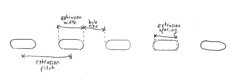
\( \text{hole size} = \text{extrusion pitch} – \text{extrusion width} \newline
\quad \quad \quad \quad \quad = \frac{\text{extrusion spacing}}{\text{infill %}} – \text{extrusion width} \newline
\text{infill %} = \frac{\text{extrusion spacing}}{\text{hole size} + \text{extrusion width}} \)
Note: “extrusion width” is the outside (maximum) width of the extrusion’s pill-shaped cross-section, whereas “extrusion spacing” is the average width of the extrusion. It is extrusion spacing that is used to calculate the extrusion pitch (distance between extrusions) based on infill percentage (percentage of volume occupied by material).
Here is a spreadsheet that calculates the infill percentages for standard mesh sizes:
Screen Thickness
I have found that fine 3D-printed screens are most likely to fail by tensile failure, i.e. when the extrusions stretch and break when excessive force is applied to them. The tensile strength of the screen is proportional to both its thickness and its infill percentage. This means that as the screen gets coarser and its infill percentage decreases — in order to maintain the same strength — its thickness must increase. (Alternatively, extrusion width could increase to keep infill percentage the same as hole size increases.) Another consideration is that the screen must also be thin enough to avoid excessive friction and allow material to easily pass through it.
I found that when \(\text{thickness} \times \text{infill %} = 0.2\text{ mm}\), the sieve was sufficiently strong. (I.E. I printed a sieve at 50% infill, with 2 0.2 mm-high layers.) I did not try any other \(\text{thickness} \times \text{infill %}\) values.
As the screen gets coarser and thicker, it is more likely to fail by bending. Such a failure mode is beyond the scope of this blog post.
Conclusion
After finding out the right print settings, I was able to print perfectly functional sieves which could sift sand as quickly and easily as any commercial sieve. The main drawback they face is a lack of durability, as they are weaker than metal sieves, and cannot be left in the sun without softening and deforming.