
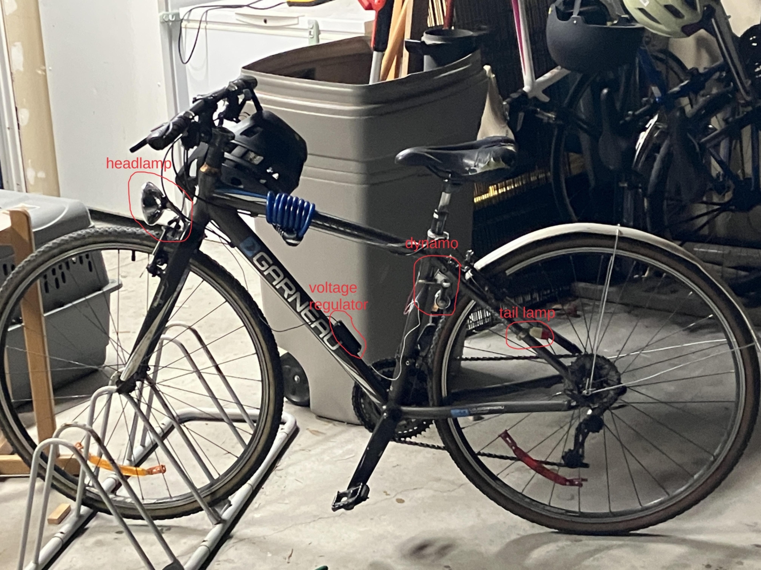
Recently finding the need to bike home in the dark, and not wanting to regularly charge a battery-powered light, I decided to buy a used bicycle dynamo (for $40) to power a front and rear bike light.
The dynamo is a bottom-bracket dynamo, which means it’s meant to be mounted on the bottom bracket (where the pedals are mounted) and is driven by the tire tread. This contrasts with bottle dynamos which are driven by the sidewall of the tire, potentially wearing out the sidewall. There was no space to mount the dynamo on my bottom bracket, but thankfully it fit just as well on the seat stay (the part connecting the seat with the rear wheel axle). To stably clamp it in place, I had to make a custom bracket out of a piece of galvanized pipe pounded flat and bent into the right shape to conform with the seat stay tubes.
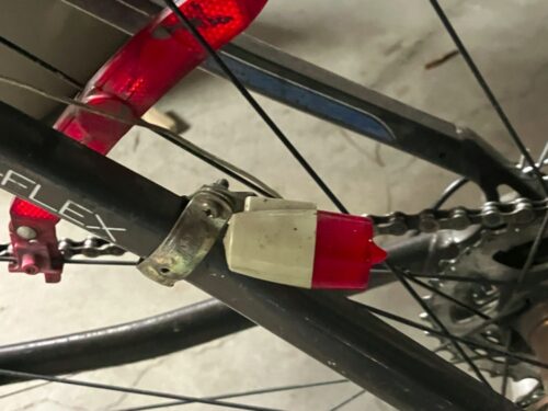
For the rear light, I bought a 1445 automotive lamp, rated at 14.4 V, 1.9 W. Since the dynamo behaves like a constant-current source, it can actually produce much higher voltages than its rated 6 V, so the rear light gets plenty bright at medium speeds. The rear light fixture that came with the dynamo required a threaded bulb, whereas the bulb I bought had a bayonet base, so I had to use a file to cut down the bayonet nubs and form a very crude thread on the base.
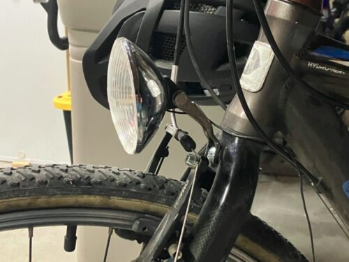
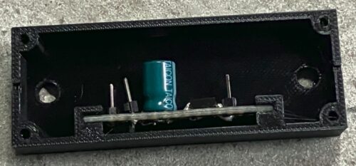
The headlamp accepts PR bulbs, the type used for older flashlights. I’m using a 4.5 – 6 V, 40 lumen LED bulb powered by a half-bridge rectifier and a 5 V linear voltage regulator soldered onto a PCB, and housed in a 3D printed case that is mounted on the water-bottle-cage holes on the bike. Since the LED barely consumes any current, its presence does not really affect the voltage outputted by the dynamo, which can still reach the higher voltage needed to power the rear light.
Everything is connected with DuPont connectors, using the bicycle frame as a ground.


Some Other Stuff I Thought About While Doing This Project
I originally wanted to use a 4.8 V, 0.75 A incandescent lightbulb instead of the LED for the headlamp. They were both bought at a local hardware store, but the incandescent bulb is a bit brighter. Unfortunately, since its current requirement is greater than the dynamo’s current, the dynamo lowers its output voltage and the lamp is very dim.
What’s needed is to convert the voltage and current from the dynamo to a decreased voltage and increased current. The obvious solution would be a transformer, but I didn’t have one on hand. Something else I tried was using a LM2596 buck converter connected to the dynamo via a rectifier, but this didn’t work since the converter is designed to operate on constant voltage; so it (to put it in very hand-wavey terms) “responds” to the need for more output current by drawing more input current, which causes the dynamo to decrease its voltage and the converter to draw yet more current.
Just to go off on a tangent here — I know the preceding effect to be true because of the following test: I set my DC power supply to a high voltage (~15 V) and low current (0.5 A), and used it to power the buck converter, which was connected to the lightbulb. When the supply was turned on, and then connected to the converter, the lamp lit very brightly, and the converter drew a relatively low current, just as expected. But when the supply was turned on with the converter already connected, the lamp was very dim; this was because the supply does not instantaneously reach full voltage, leading to the converter initially “demanding” higher current, causing the supply to enter constant-current mode and limit the voltage available.
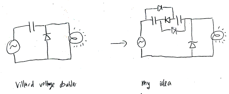
Something else I thought of was to make a sort of current-doubling circuit by modifying a Villard voltage doubler. From my understanding, this circuit works by charging a capacitor through a diode when the AC voltage is in reverse, then discharging it when it is forward. My idea was to replace the capacitor with two capacitors, linked by diodes so that they charge in series but discharge in parallel. Trying the circuit showed no advantages, though this may be because all the extra diodes introduced caused a big voltage drop. Attempts to simulate the circuit in Qucs and Simulide proved unsuccessful, so I’m not sure if the concept is even sound.
UPDATE: 2025-03-15
I finally worked out all the simulation kinks in Qucs, and the circuit doesn’t work.
One response to “Bicycle Lighting”
[…] of my bicycle-lighting project involved crimping a splitter cable to split the output of the dynamo to the front and rear lamps. I […]