I’ve been wanting to make a die filer for some time now. It is a power-driven file that allows you to easily cut complex shapes. Die filers are not meant for a very high material-removal rate; rotary files and cold-chisels exist for that purpose.
Design
Parts of the Die Filer
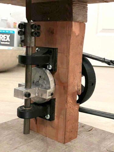
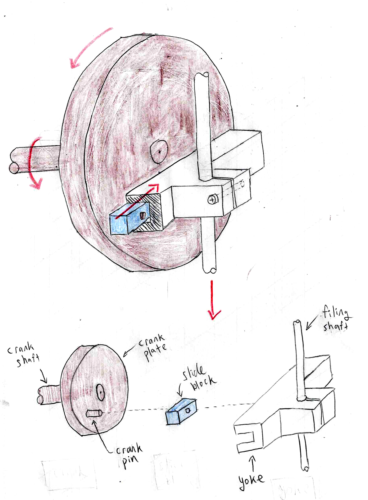
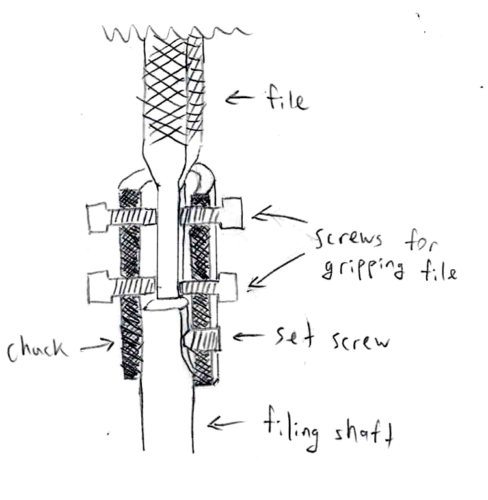
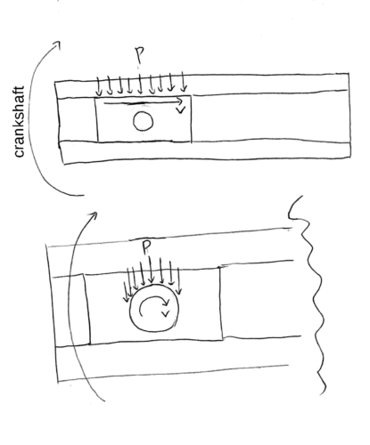
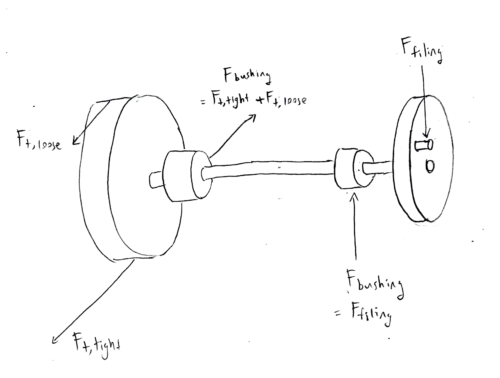
The file is run up and down on a “filing shaft”, which is supported by a “top bushing” and a “bottom bushing”. A “chuck”, consisting of a steel sleeve and set screws, couples the file and filing shaft. The filing shaft is driven up and down with a scotch-yoke mechanism, consisting of a “crankshaft”, “crank plate”, “crank pin”, “slide block”, and “yoke”. The crankshaft drives the crank pin and slide block in a circular motion, and the slide block moves the yoke (which is clamped to the filing shaft) up and down.
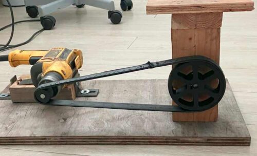
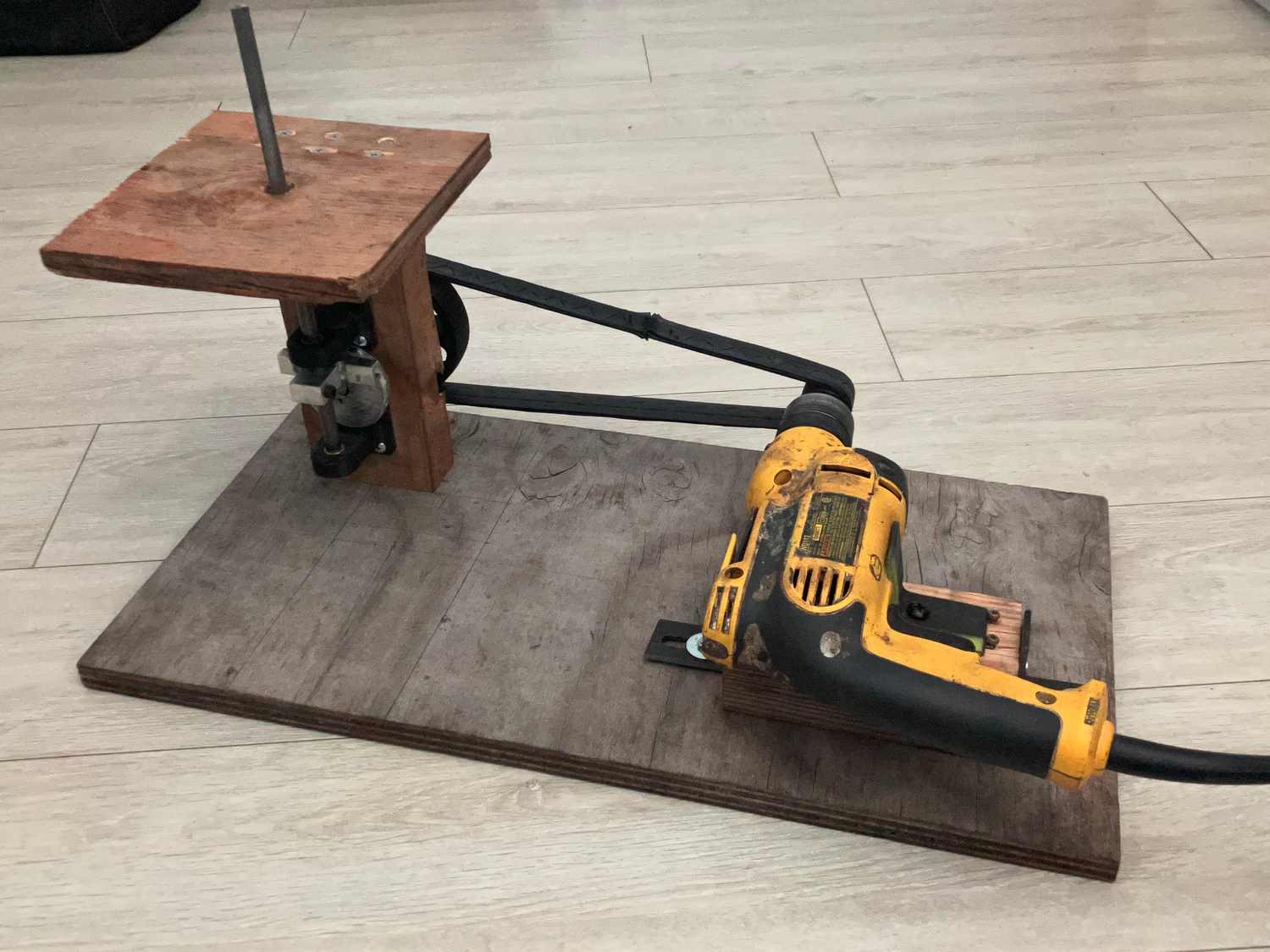
The die filer is powered with a hand drill through a flat belt drive. The drill is clamped to a block of wood using steel angles, and the block of wood is screwed to the same mounting plate as the column.
The main tools I had to manufacture this die filer were: a 3D printer, a drill press, a hacksaw, cold chisels, files, a wood saw, and a wood plane. The available materials were PLA (polylactic acid) 3D-printing filament, scrap 6061-T6 aluminium from my school’s machine shop, scrap construction lumber, and hot-rolled structural steel from the hardware store. I also used store-bought parts like screws, bushings, shafts, etc.
Math Formatting Notes
- the subscript “operating” denotes operating loads; all other loads are assumed to be design loads
- the subscript “u” denotes the ultimate load before bad things happen
- the subscript “max” denotes the maximum cyclical design load
- the subscript “avg” denotes the average cyclical design load
A spreadsheet of my calculations, including variable definitions, is here:
Design Loads and Specifications
Most small die filers are run with a short stroke and a high speed. Thinking that a longer stroke and slower rotational speed would be more efficient and reduce file wear, I decided on a stroke of 40 mm for my design. Based on random internet surfing, 480 strokes per minute (8 strokes per second) seems like a good speed. Since the scotch yoke produces a sinusoidal motion, the average sliding speed and maximum sliding speed (used for bushing wear calculations) are different.
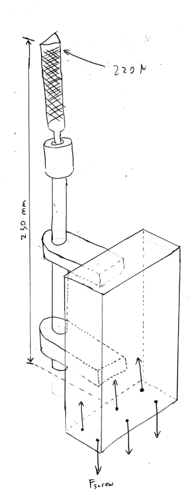
Using a luggage scale, I estimated that I push the file down with about 45 N of feeding force when filing “normally”, so with a safety factor of 1.5 I used a design load of 68 N. Using a handwavey estimate of the friction coefficient between file and part, I estimated that 68 N of cutting force were needed to pull the file up and down. The filer should also be able to structurally undamaged by the maximum force that a person can exert, which is about 40–50 lb (180–220 N) at chest level for an adult male according to a figure from Ullman’sThe Mechanical Design Process. I’ll use 220 N.
\(
F_{feed} = F_{feed,operating} \times k_{load} = 45\text{ N} \times 1.5 = 67.5\text{ N} \newline
F_{cutting} = μ \times F_{feed} = 1 \times 67.5\text{ N} =67.5\text{ N} \newline
F_{feed,max} = 220\text{ N} \newline
r = stroke/2 = 40\text{ mm} / 2 = 20\text{ mm} \newline
f = 480\text{ strokes/min} = 8\text{ strokes/s} \newline
ω = 2πf = 2π \times 8 \text{ strokes/s} = 50.3\text{ rad/s} \newline
v_{max} = rω = 0.020\text{ m} \times 50.3\text{ rad/s} = 1.01\text{ m/s} \newline
v_{avg} = 2 \times stroke \times f = 2 \times 0.040\text{ m/stroke} \times 8 \text{ strokes/s}= 0.640\text{ m/s} \newline
τ_{crank} = τ_{crank,operating,max} = F_{feed}r = 67.5\text{ N} \times 20\text{ mm} = 1350\text{ Nmm}
\)
Structural Calculations
Filing Shaft
The filing shaft is a 3/8″ (9.53 mm) cold-rolled 1018 steel round bar. When the file is loaded with its maximum structural load of 220 N, this results in a maximum stress of 220 MPa, compared the yield stress of 370 MPa.
\(
M = F_{feed,max} \times a = 220\text{ N} \times 85\text{ mm} = 18700\text{ Nmm} \newline
I = \frac{\pi}{64} d^4 = \frac{\pi}{64} (0.375\text{ in})^4 = 404 \text{ mm}^4 \newline
σ_{max} = \frac{Mr}{I} = \frac{18700 \text{ Nmm} \times 4.76\text{ mm}} {404 \text{ mm}^4} = 220 \text{ MPa} \newline
k_{safety} = σ_{yield}/σ_{max} = 370\text{ MPa} / 220\text{ MPa} = 1.68
\)
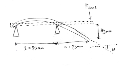
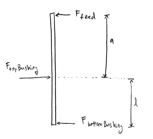
When loaded with the normal feeding force of 67.5 N, the linear deflection will be 0.491 mm where the load is applied, and the angular deflection will be about 0.281°. This angular deflection is probably less than the manufacturing error of my wooden parts.
\(
Δy_{max} = \frac{Fa^2}{3EI}(l-a) \newline
\quad =\frac{67.5\text{ N} \times (85\text{ mm})^2}{6 \times 200000\text{ MPa} \times 404\text{ mm}^4} (80\text{ mm} – 85\text{ mm}) = 0.332\text{ mm} \newline
\frac{\text{d}y}{\text{d}x}_{max} = \frac{F}{6EI}(3a^2 + 2al) \newline
\quad = \frac{67.5\text{ N}}{3 \times 200000\text{ MPa} \times 404\text{ mm}^4}(3(85\text{ mm})^2 + 2(85\text{ mm})(80\text{ mm})) = 0.00491 \newline
θ \approx \frac{\text{d}y}{\text{d}x} = 0.00491\text{ rad} = 0.281°
\)
Column
The maximum load results in a moment of 50.6 Nm at the base of the column, which is resisted by its mounting screws. Using the US Forest Service’s formula for the stripping strength of wood screws, and reducing stripping strength by 25% to account for screws driven into end-grain, the column mounting screws (#10 size) have a stripping strength of 1200 N. Then, making the conservative assumption that the screws are the only supports for the column (i.e. ignoring contact between column and base), the three pairs of screws can withstand 93.6 Nm before stripping.
I didn’t consider the effect of shear on the column.
\(
M = F_{feed,max} \times l = 220\text{ N} \times 230\text{ mm} = 50600\text{ Nmm} \newline
F_{screw,u} = 108.25\frac{\text{N}}{\text{mm}^2(\text{g/cm}^3)^2} \times d_{screw} \times l_{engagement} \times \rho_{wood}^2 \times 0.75 \newline
\quad = 108.25\frac{\text{N}}{\text{mm}^2(\text{g/cm}^3)^2} \times 0.19\text{ in} \times 25\text{ mm} \times (0.35\text{g/cm}^2)^2 \times 0.75 = 1200\text{ N} \newline
M_{u} = F_{screw, max} \times x_{pair} \times n_{pairs} = 1200\text{ N} \times 26\text{ mm} \times 3 = 93600\text{ Nmm}\newline
k_{safety} = M_u/M = 93600\text{ Nmm} / 50600\text{ Nmm} = 1.85
\)
Pulley Drive Design
The ideal belting material would be polyurethane, since its low elastic coefficient allows it to be stretched in place onto fixed pulleys, instead of requiring a complicated tensioning mechanism; for this project, I made a similar sort of belt made out of 3 plies of butyl rubber from an old bicycle inner tube.
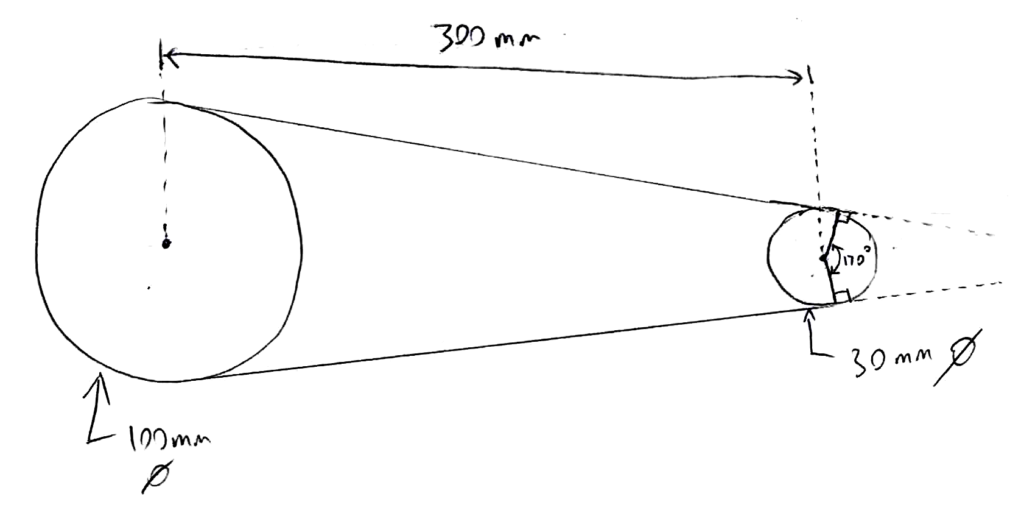
The hand drill used to power the die filer has a running speed of ~1500 RPM, which needs to be geared down by roughly 3:1 to produce the desired speed of 480 strokes per minute. With a 100 mm diameter driven pulley, this translates to a driving pulley with a diameter of 30 mm.
With a center distance of 300 mm, an arc of contact of about 170° (2.97 rad) can be achieved on the driven pulley; in this case, the minimum required tension to avoid slip is 19.0 N. With a luggage scale, I determined that a stretch of 150 mm would produce the required tension on the 600 mm long belt. As a handwavey estimate, I’ll put the final belt stretch at 200 mm (producing a measured tension of 27 N) to avoid any slippage.
\(
F_{t,min}=\frac{τ}{d} \times \frac{e^{\mu \theta} + 1}{e^{\mu \theta} – 1} \newline
\quad = \frac{1350\text{ Nmm}}{100\text{ mm}} \times \frac{e^{0.6 \times 2.97\text{ rad}} + 1}{e^{0.6 \times 2.97\text{ rad}} – 1} = 19.0\text{ N} \newline
F_t = 27\text{ N}
\)
Plain Bearing Calculations
Because the motion of the file is reciprocating, and there is no constant lubricant supply, I’m assuming that the die filer’s bushings operate mainly under conditions of boundary lubrication (rather than hydrodynamic lubrication, in which there is a constant film of high-pressure lubricant between surfaces). As such, I’m going to evaluate the bearing pressure, surface speed, pressure × velocity (PV) value, and wear rate of the moving parts, as is usual when designing boundary-lubricated bearings.
Information on the bushing materials was obtained from Shigley’s 10th-edition Mechanical Engineering Design, and Machinery’s Handbook. I also used the table of motion- and environmental-based wear-increasing factors from Shigley.
The results are summarized in the following chart. Overall, the top filing bushing saw the greatest loads, since the file is cantilevered off (instead of being supported between) the filing bushings.t

And here are the equations:
Top Filing Bushing
\(
A_{contact} = l \times d = 0.5\text{ in} \times 0.375\text{ in} = 121\text{ mm}^2 \newline
F = F_{feed}\frac{l+a}{l} = 67.5\text{ N}\frac{80\text{ mm} + 85\text{ mm}}{80\text{ mm}} = 139\text{ N} \newline
P = F/A_{contact} = 139\text{ N} / 121\text{ mm}^2 = 1.15\text{ MPa} \newline
P_u = 4500\text{ psi} = 31\text{ MPa} \newline
v_{max} = 1.01\text{ m/s} \newline
v_u = 1500\text{ ft/min} = 7.6\text{ m/s} \newline
PV = P \times v_{avg} = 1.15\text{ MPa} \times 0.640\text{ m/s} = 0.737\text{ MPa m/s} \newline
PV_u = 50000\text{ psi ft/min} = 1.8\text{ MPa m/s} \newline
K_{wear} = 102(10^{-10}) \frac{\text{in}^3\text{min}}{\text{lb ft hr}} = 2.05(10^{-6})\frac{\text{mm}^3}{\text{Nm}} \newline
v_{wear} = PV \times K_{wear}k_{motion}k_{environment} \newline
\quad = 0.737\text{ MPa m/s} \times 2.05(10^{-6})\frac{\text{mm}^3}{\text{Nm}} \times 4 \times 3 = 0.0652\text{ mm/hr} \newline
\)
Slide Block and Yoke
\(
A_{contact} = l \times w = 0.75\text{ in} \times 0.25\text{ in} = 121\text{ mm}^2 \newline
F = F_{cutting} = 67.5\text{ N} \newline
P = F/A_{contact} = 67.5\text{ N} / 121\text{ mm}^2 = 0.558\text{ MPa} \newline
P_u = 28\text{ MPa} \newline
v_{max} = 1.01\text{ m/s} \newline
v_u = ???? \newline
v_{avg} = 0.64\text{ m/s} \newline
PV = P \times v_{avg} = 0.558\text{ MPa} \times 0.64\text{ m/s} = 0.357\text{ MPa m/s} \newline
PV_u = ???? \newline
v_{wear} = PV \times K_{wear}k_{motion}k_{environment} \newline
\quad = 0.357\text{ MPa m/s} \times 4.0(10^{-6})\frac{\text{mm}^3}{\text{Nm}} \times 4 \times 3 = 0.0617\text{ mm/hr}
\)
Crank Pin and Slide Block
\(
A_{contact} = l \times d = 0.25\text{ in} \times 0.125\text{ in} = 20.2\text{ mm^2} \newline
F = F_{cutting} = 67.5\text{ N} \newline
P = F/A_{contact} = 67.5\text{ N} / 20.2\text{ mm}^2 = 3.35\text{ MPa} \newline
P_u = ???? \newline
v = \frac{d}{2}ω = \frac{0.25\text{ in}}{2} 50.3\text{ rad/s} = 0.0798\text{ m/s} \newline
v_u = ???? \newline
PV = P \times v = 3.35\text{ MPa} \times 0.0798\text{ m/s} = 0.267\text{ MPa m/s} \newline
PV_u = ???? \newline
v_{wear} ≤ PV \times K_{wear, aluminium}k_{motion}k_{environment} \newline
\quad = 0.267\text{ MPa m/s} \times 4.0(10^{-6})\frac{\text{mm}^3}{\text{Nm}} \times 1.3 \times 3 = 0.0150\text{ mm/hr}
\)
Front Crankshaft Bushing
\(
P = \frac{F_{cutting}}{ld} = \frac{67.5\text{ N}}{0.5\text{ in} \times 0.375\text{ in}} = 0.558\text{ MPa} < P_u = 31\text{ MPa} \newline
v = \frac{d}{2} ω = \frac{0.375\text{ in}}{2} \times 50.3\text{ rad/s} = 0.239\text{ m/s} < v_u = 7.6\text{ m/s} \newline
PV = 0.558\text{ MPa} \times 0.239\text{ m/s} = 0.134\text{ MPa m/s} < PV_u = 1.8\text{ MPa m/s} \newline
v_{wear} = PV \times K_{wear}k_{motion}k_{environment} \newline
\quad = 0.134 \text{ MPa m/s} \times 2.05(10^{-6})\frac{\text{mm}^3}{\text{Nm}} \times 1.5 \times 3 = 0.00444\text{ mm/hr}
\)
Back Crankshaft Bushing
\(
F = 2F_{t,belt} = 2 \times 27\text{ N} = 54\text{ N} \newline
P = \frac{F}{ld} = \frac{54\text{ N}}{0.5\text{ in} \times 0.375\text{ in}} = 0.446\text{ MPa} < P_u = 31\text{ MPa} \newline
v = \frac{d}{2} ω = \frac{0.375\text{ in}}{2} \times 50.3\text{ rad/s} = 0.239\text{ m/s} < v_u = 7.6\text{ m/s} \newline
PV = 0.446\text{ MPa} \times 0.239\text{ m/s} = 0.107\text{ MPa m/s} < PV_u = 1.8\text{ MPa m/s} \newline
v_{wear} = PV \times K_{wear}k_{motion}k_{environment} \newline
\quad = 0.107 \text{ MPa m/s} \times 2.05(10^{-6})\frac{\text{mm}^3}{\text{Nm}} \times 1.5 \times 3 = 0.00355\text{ mm/hr}
\)
Calculations for Set Screws
Almost all of the shaft connections on this die filer are done with #10 set screws: the driving pulley to the motor shaft, the driven pulley and crank plate to the crank shaft, and the file holder to the filing shaft. The crank pin and front crank bearing are also secured with set screws. The yoke is secured to the filing shaft with a clamping connection.
According to Unbrako’s Socket Products Engineering Guide, a #10 cup-point set screw has an axial holding power of 2400 N, which translates to a torsional holding power of 11.4 Nm for a 3/8″ shaft. With an axial load of 67.5 N and a torsional load of 1.35 Nm, the safety factors are 35 and 8.38 respectively, exceeding the recommended “4.0-8.0 for various dynamic situations”.
Axial load
\(
F_u = 2400\text{ N} \newline
F = F_{cutting} = 67.5\text{ N} \newline
k_{safety} = F_u/F = 2400\text{ N} / 67.5\text{ N} = 35.6
\)
Torsional Load
\(
τ_u = F_u \times \frac{d}{2} = 2400\text{ N} \times \frac{0.375\text{ in}}{2} = 11430\text{ Nmm} \newline
τ = τ_{crank} = 1350\text{ Nmm} \newline
k_{safety} = τ_u / τ = 11430\text{ Nmm} / 1350\text{ Nmm} = 8.47
\)
Manufacturing
To reiterate from before, the tools I used were a 3D printer, a drill press, cold chisels, and files. The base, column, and table are made of wood, while the bearing blocks and pulleys were 3D-printed, and the crank plate and yoke were machined from aluminium.
What Needs to Be Precise?
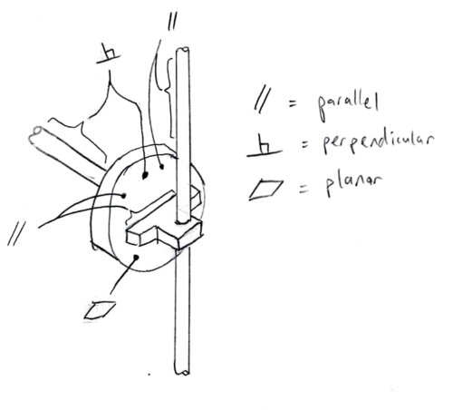
The filing shaft bushings and crankshaft bushings must be aligned to ensure that neither shaft binds up. This is achieved by having flat, parallel faces on the wooden column, and precisely-made bearing blocks.
In order for the table to be supported perpendicular to the file, the end of the column should be square with its faces, and also the bearing blocks should be aligned perpendicular to the end. The length of the column is not particularly important.
Ample clearance between screws and mounting holes allows all bearing blocks to be adjusted slightly to eliminate binding, and produce the proper angle between shafts.
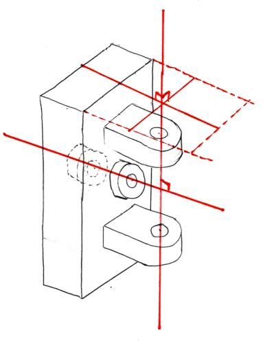
Horizontal and vertical deviations in the crankshaft position are unimportant, so long as the the slide block stays within the yoke, and the yoke doesn’t hit the filing shaft bearings. However, the filing shaft must be constrained rotationally with a minimum of play, which is accomplished by front filing bearing pushing the crank plate against the yoke with a minimum of clearance. The face of the crank plate must be square with the crank shaft, and parallel to the yoke and the filing shaft, which means the crankshaft must be perpendicular to the filing shaft.
All parts of the scotch yoke mechanism should run freely, without any binding, but a little play is permissible between parts.
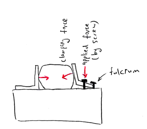
The chuck does not have to be precise at all. It basically consists of two “four-jaw chucks” (using screws as jaws) on top of each other, allowing the file’s angle to be finely adjusted.
Woodworking
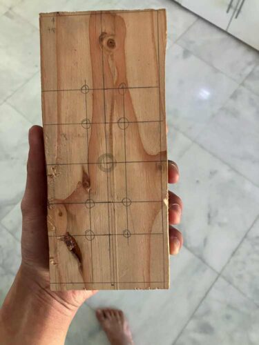
To make the column I first planed one face flat with a hand plane, and then use a local makerspace’s wood planer to cut the opposite face parallel, and a miter saw to square the ends. With enough skill and practice, I think I could have done it entirely at home just using a hand saw and a plane and maybe some home-made jigs.
Plasticworking
The bearing blocks and pulleys were 3D-printed for convenience and precision. The top and bottom filing bearings, and the back crankshaft bearing were press-fit (using a drill press to push them in), while the front crankshaft bearing was installed in a clearance hole with a set screw, so that it could be slid back and forth. The pulleys were secured to their shafts using set screws installed in captive nuts.
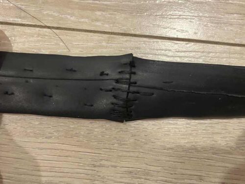
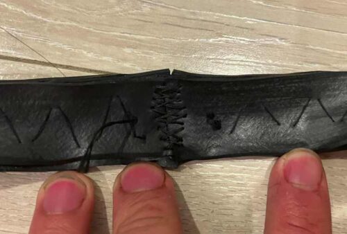
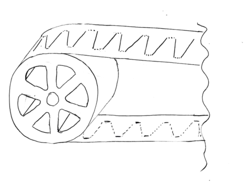
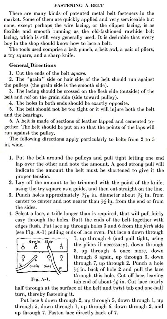
As mentioned before, the drive belt was made of 3 plies of bicycle inner-tube rubber, sewn together. Since it’s preferred that all stitches on the pulley side of the belt to be straight to avoid getting torn out, and also the stitch must have some zig-zag so it can stretch, I used something similar to a catch stitch. The ends of the belt were sewn together using the method recommended in Burghardt and Axelrod’s Machine Tool Operation.
Metalworking
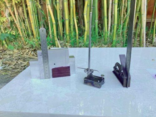
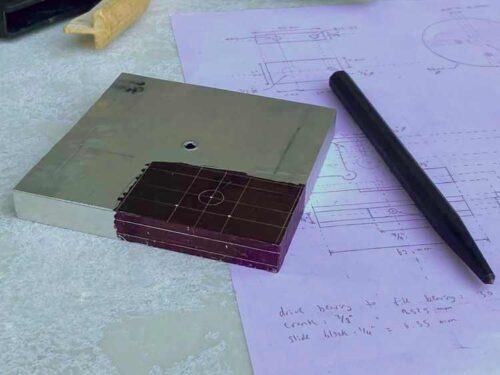
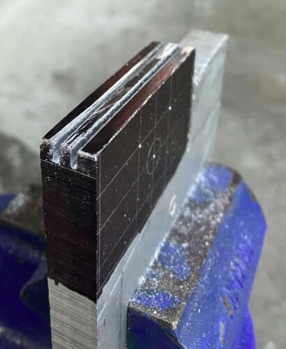
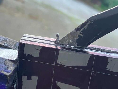
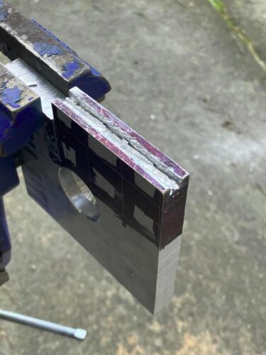
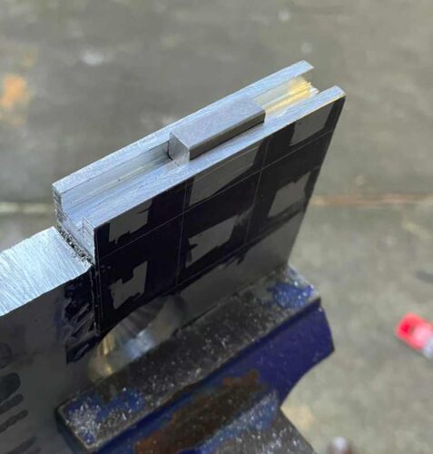
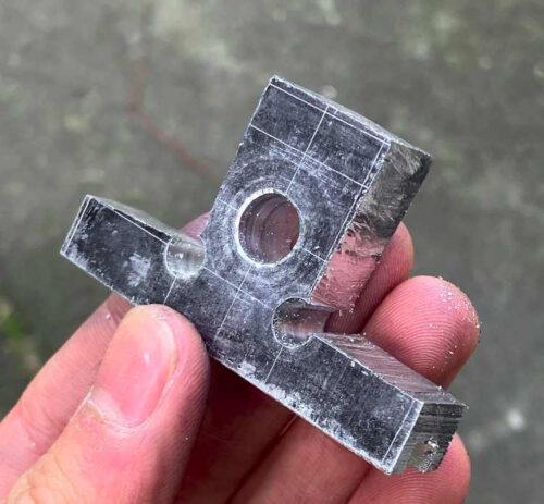
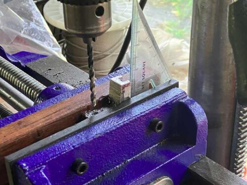
The crank plate and yoke were machined from 6061-T6 aluminium plate stock. To put it briefly, their shapes were laid out using a surface gage, scriber, and dividers; roughly cut out with a hacksaw; and filed to the layout lines. To machine the yoke’s slot, the sides were roughly sawn out with a hacksaw, then a cape chisel (which I made by grinding down a flat chisel) was used to remove the material in between, and then a file was used to finish it. Holes were located by laying them out, then center-punching, spot drilling, and finally drilling them to their final size. For holes drilled edgewise, the part was held in a cross-slide vise, or clamped to an “angle plate” (actually just a block of metal with squared faces).
The chuck was made from a piece of 3/4″ hot-rolled mild steel, though it would have been easier to machine from a piece of square stock. As before, holes were laid out and center-punched. Since I didn’t have any V-blocks to properly hold the round stock, and the holes didn’t need to be very precise, I just gripped it in a trigger-clamp, and eyeballed the setup.
Additionally, the shafts had to be cut to length with a hacksaw, and flats were filed into them for set screws. The crank block was a store-bought square machine key, with a hole drilled into it for the crank pin. The crank pin was a store-bought hardened-steel dowel pin.
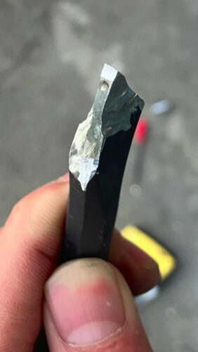
Finally, the file was made from a hand file, which was modified to fit the die filer. Since hand files cut on the “push” stroke, its tang was cut off, and the tip was turned into a round shank by grinding it with a Dremel while spinning it with a drill press.
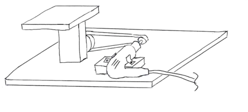
THE FINISHED DIE FILER!!!!